
Liquid Cooling Data Center Design: CDU Sizing, Coolant Derates and Hydraulic Reality
Liquid-cooled halls are designed or broken in three places most spec sheets skip: what the CDU really delivers on glycol coolant, whether N+1 exists in the pipes and not just the equipment list, and what the coolant actually is. This page summarizes the published analysis and links the free drawing set that carries the interfaces.
Why Liquid Cooling Is Now the Baseline
GB300-class rack systems — on the order of 135–150 kW per rack — are liquid-cooled by design; air cannot carry that heat off a single floor tile. The reference design documented on this site uses a 136 kW-per-rack, direct-liquid-cooled design basis, which moves the central cooling questions from air handlers to the coolant loop: CDU capacity, coolant properties, hydraulic paths and the electrical feeds that keep the loop alive. Those questions are where liquid-cooling designs actually succeed or fail, and they are the subject of the direct liquid cooling and CDU cluster of the Data Center Lab.
The CDU Is Not a Catalog Number
A coolant distribution unit (CDU) carries a nameplate rating measured on water — but AI halls commonly run propylene-glycol mixes for freeze and corrosion protection. The Lab’s modeled analysis shows a water-rated 1.5 MW CDU delivers about 1.20–1.28 MW on PG25: sizing a hall on nameplate figures quietly erases 15–20% of cooling capacity. The coolant itself is the reason: PG25 is not “water plus 4.5% volume” — its viscosity and heat capacity change the thermal and hydraulic arithmetic together.
N+1 on the Equipment List Is Not N+1 in the Pipes
Redundancy claims for CDUs are usually counted on the equipment schedule. The Lab’s hydraulic analysis shows N+1 on the CDU list is not N+1 in the pipes: whether the spare unit can actually serve a rack row depends on the piping topology between them, not on the count. The hydraulics and transients cluster works the same discipline through flow balancing and failure transients.
Where This Lives in the Drawing Set
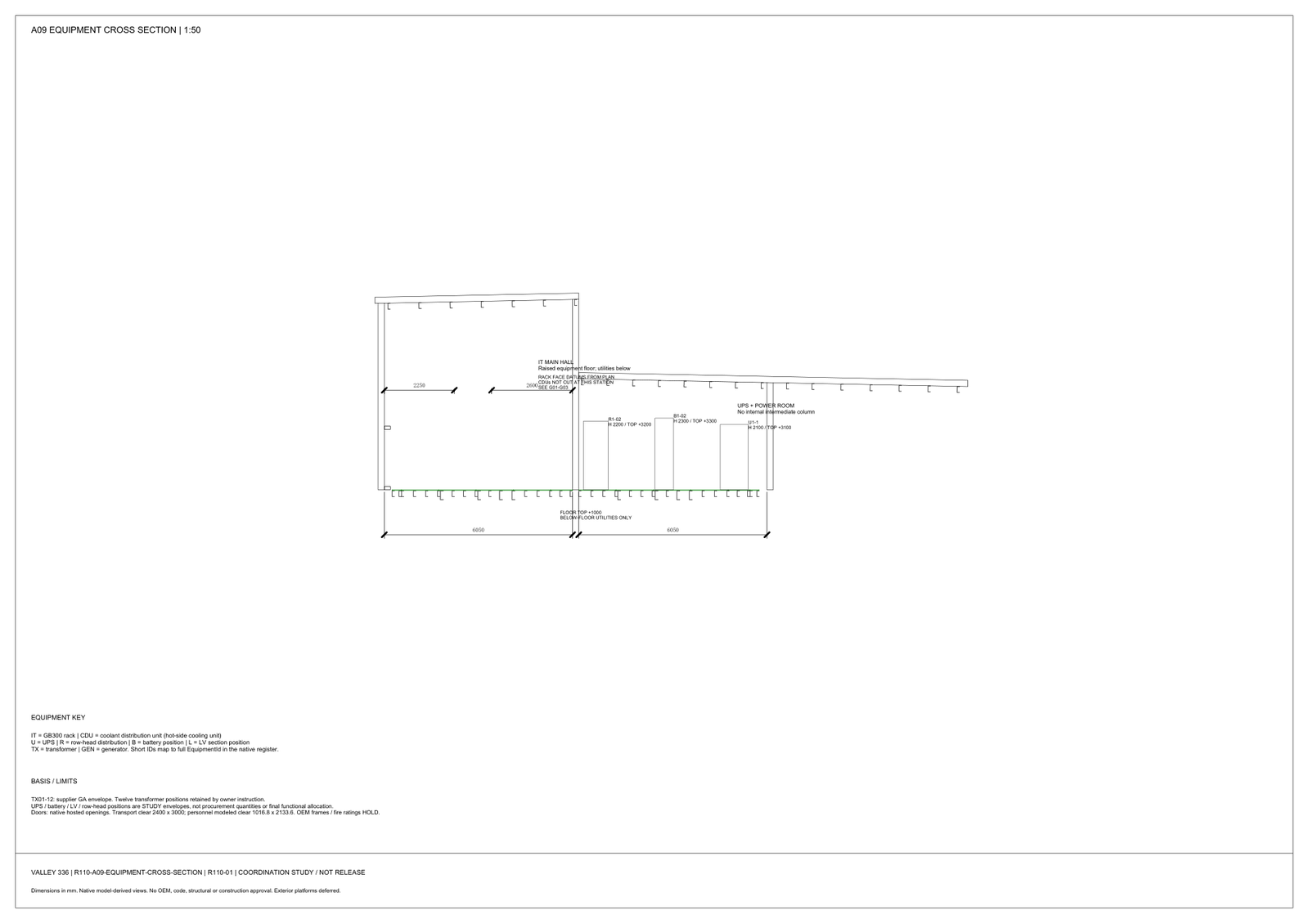
The published reference drawings carry the liquid-cooling interfaces across disciplines: the equipment plans in the structural set show CDU positions along the hall, the equipment cross section shows rack, battery and UPS envelope heights in the same bay, and the 88-page electrical book carries the protected feeds for the cooling plant. Cooling, electrical and structure are one coordinated layout — which is the point of downloading the whole set rather than a single-discipline diagram. The dedicated liquid-cooling reference design PDF (38 pages) — the functional P&ID and coordination set for the 90-rack layout — was added to the downloads in October 2026.
Download the Drawing Set
Every document is a direct PDF download — no registration, no email gate — with a published SHA-256 checksum on the downloads page:
- Electrical Drawing Book — Public Edition P1 (14 MB, 88 pages)
- Structural Document Set — Public Edition P1 (84 MB, 170 pages)
- GPU Hall Network Reference Design — Public Edition P2 (1.6 MB, 75 pages)
- Liquid Cooling Reference Design — Public Edition P1 (3.1 MB, 38 pages)
- BIM Machine-Audit Sample Pack (5 KB, 4 artifacts + README)
- Storage-Capacity Model — Companion Code (34 KB, code + dataset)
- GPU Hall Design Readiness Checklist (7 KB, 2 pages)
- Machine-Audit Template Pack (3 KB, 3 templates + README)
- Electrical + Structural + Network — Combined ZIP (97 MB, 3 documents)
Published at Design Development — Public Edition P1 status: reference designs for study and evaluation, not construction issues, not sealed by an Engineer of Record. Reuse follows the attribution terms stated inside each document.
Common Questions
What does a CDU do in a liquid-cooled data center?
A coolant distribution unit (CDU) is the interface between the facility water system and the IT coolant loop: it exchanges heat, sets coolant supply temperature and pressure, and distributes flow to the rack rows. Its real capacity depends on the coolant used, not just the nameplate.
How much capacity does a CDU lose on glycol coolant?
The Lab's modeled analysis of a water-rated 1.5 MW CDU shows about 1.20–1.28 MW of delivered capacity on PG25 (25% propylene glycol) — a 15–20% derate that must be designed in, not discovered at commissioning.
Is N+1 CDU redundancy enough for a GPU hall?
Only if the hydraulic topology lets the spare unit actually reach the load: N+1 on the equipment list is not N+1 in the pipes. The piping between CDUs and rack rows decides whether the redundancy is real.
Is there a real liquid-cooling P&ID for data centers available to study?
Yes — the downloads on this site include a 38-page functional P&ID and coordination set for a 90-rack, five-group direct-liquid-cooling layout: cold-source selection trains, CDU groups with A/B secondary loops, six-rack unit details and buffer/transfer design requirements. Free direct download, SHA-256 verified.
What rack density forces a move to direct liquid cooling?
Current GB300-class rack systems, on the order of 135–150 kW per rack, are liquid-cooled by design. The reference design on this site uses 136 kW per rack with direct liquid cooling as its basis — roughly ten times conventional air-cooled hall density.
Questions about any sheet or parameter: inquiry@kkdatasvc.com or the contact page.