This page presents reference exploration of plan interpretation, steel frame logic, BIM-ready data, model checks, kit staging, logistics planning, and cost modeling. The materials support workflow study only.
Real Field Evidence
Steel frame, wall, BIM, kit, and cost logic use field-verifiable assembly examples as reference for review.
This is a public R&D update. Final structure, code compliance, pricing, permits, logistics, and installation scope require project-specific professional review.
K&K R&D maintains reference work on a modular housing workflow. The materials connect plan interpretation, structural logic, wall and MEP planning, BIM-ready data, model checks, container loading, field reassembly planning, and cost modeling for review.
Diagrams, photos, counts, and descriptions serve as support for ongoing R&D study. They do not represent completed designs, validated systems, or offered products. A visitor should interpret the content as internal reference material only.
Review Base Plan Inputs
The workflow review begins with a customer-recognized base plan. Layout, room relationships, window and door positions, heights, and major functional intent are treated as source inputs. This preserves original design intent for further review.
In the current reference model, geometry, structure, wall systems, MEP routing assumptions, container loading logic, and cost data are connected. The model serves as a sample for workflow refinement.
Diagram illustrating one explored mapping from prefab planning inputs to model data, checks, kits, logistics, and cost evidence.
Review Steel Frame Logic
For high-wind application scenarios, the R&D direction studies a 200 MPH design target as an engineering objective, not a certification claim. The approach organizes structure around load paths, defined openings, connection zones, and reassembly logic rather than adding material uniformly.
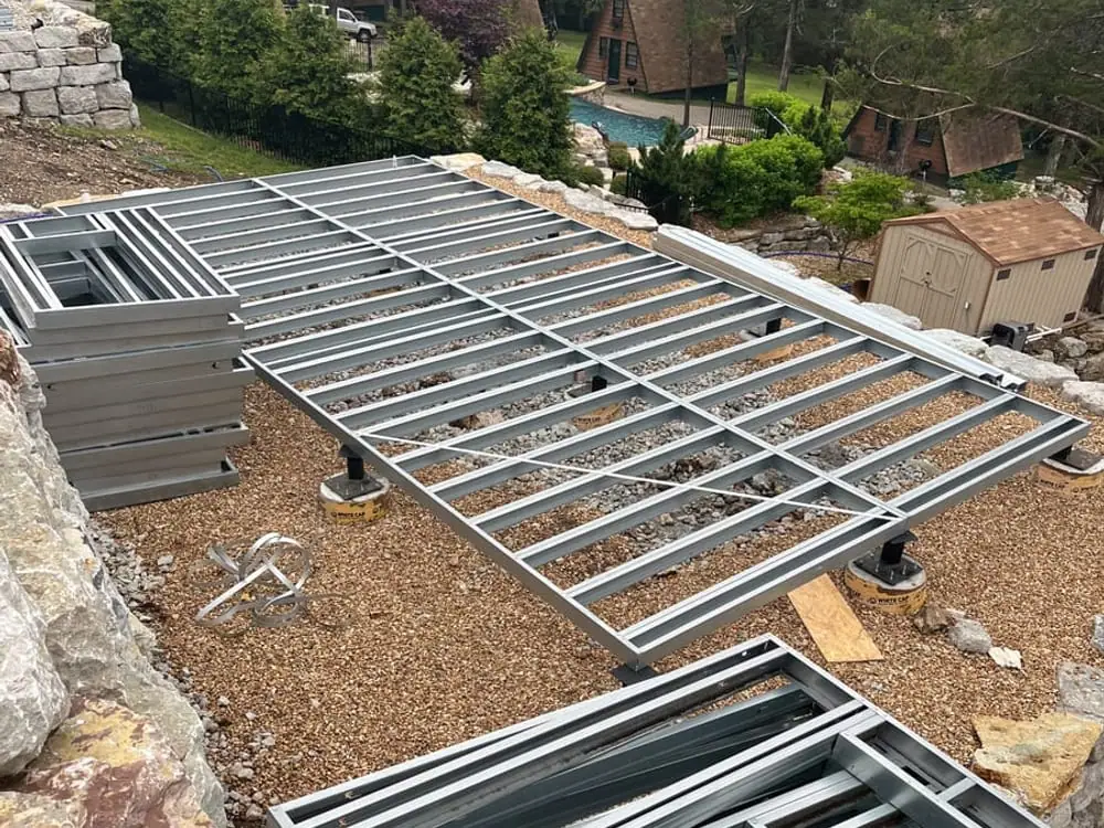
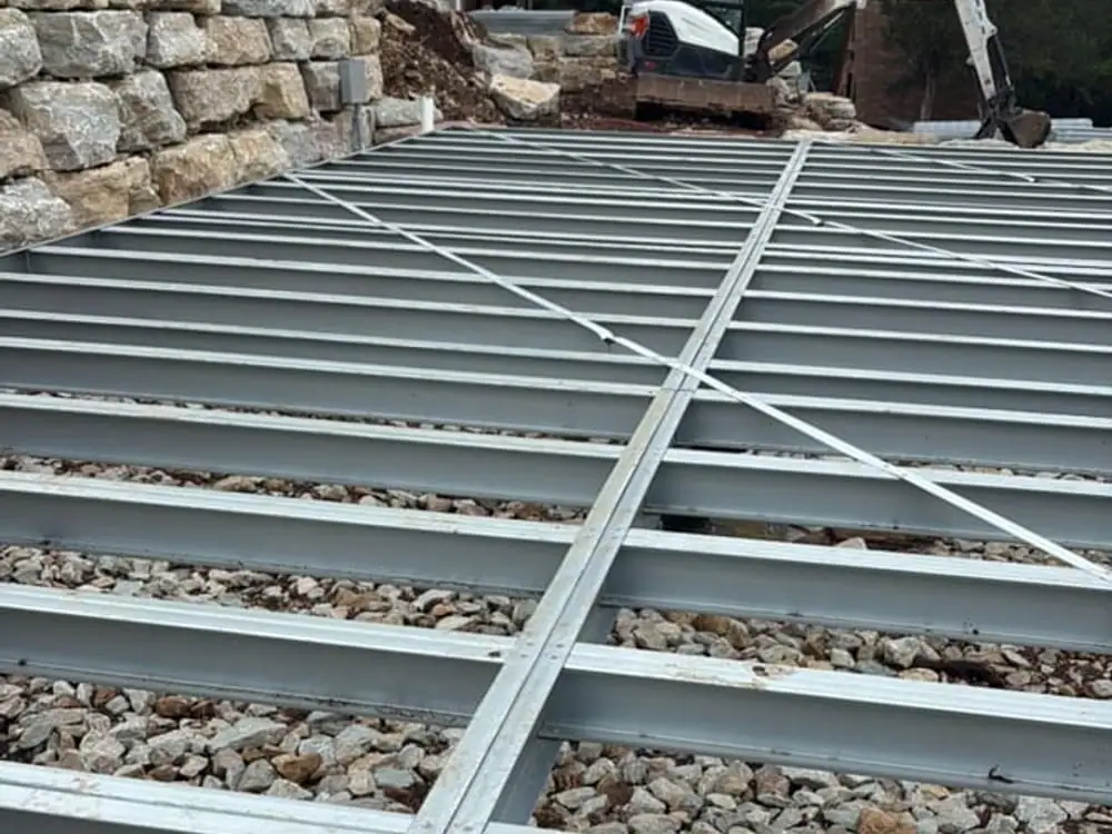
The reference workflow uses HSS main frame members for the primary load path, C/U type secondary framing for walls, floors, and roof support, reinforced door and window openings, diaphragm-style roof and floor elements, and defined anchor and connection locations. The package is shaped to support factory drilling, welding, numbering, and prefit checks for field reassembly.
Field steel grid used to keep load paths, spacing, and reassembly logic readable in the reference.
See Kit Staging from Load Items
The reference model groups 561 load items into 159 stage-ready kits. Kits are organized by installation phase, structural zone, wall cassette, MEP interface, floor and roof layer, connection hardware, and access panel area.
The approach moves some sequencing decisions into the design and factory package. In the model, steel members group by installation order, wall cassettes by sets, fasteners by node, MEP interfaces in service zones, finish and access panels separate from structural items, and floor/roof layers loose-packed where transport risk is lower.
Review Lightweight BIM Data and Model Checks
The R&D center maintains a machine-readable inspection package for the reference model. Data includes component IDs, bounding boxes, centerlines, component types, system ownership, connection nodes, allowed overlaps, access areas, and container-loading context.
The model supports review by people and by software. Checks under test include collision review, floating wall conditions, duplicated wall logic, door and window conflicts, MEP route chase alignment, access panel coverage, node reachability, fastener intrusion into finish areas, and load dimensions for 40HQ container logic.
Model checking map connecting R&D model data, node checks, MEP routes, kit order, field evidence, and cost scope.
Review Wall, Insulation, Finish, and MEP Configurations
The current base configuration studies an Economy+ direction. It uses MgO board as substrate or structural sheathing, interior PVC/WPC/wood-look finish panels, rock wool for insulation and acoustic control, metal exterior finish over WRB and MgO layers, and a roof terrace direction using TPO waterproofing with removable WPC deck boards.
In the reference, MEP rough-in keeps key interfaces serviceable and access areas protected. Factory-suitable work is assigned to the factory while access for inspection, testing, and maintenance is preserved.
Field kit review map connecting kit IDs, node connections, site install reference, and cost scope evidence.
Review Cost Modeling for Early Planning
The R&D center tests a V4 cost model so early budget direction does not rely on a single guessed total. Each cost node links to quantity source, quantity formula, price source, evidence level, included scope, excluded scope, dependency, and risk sensitivity.
For the reference model, internal figures cover factory goods and services, ocean freight, U.S. installation labor, and tariff sensitivity. These are not public fixed quotes and exclude project-specific foundation, permit, site access, utility, engineering, or jurisdictional items. The figures help assess whether a budget direction is plausible before deeper quote and engineering work.
Review Factory Planning and Reassembly Logic
The reference workflow organizes factory tasks to support field predictability. The model includes a 25-working-day factory schedule, 12 WBS work packages, steel receiving, cutting, drilling, welding, test fitting, numbering, wall cassette production, MEP preassembly and testing, floor and roof pre-cutting, disassembly, packing, photo records, and a 2x40HQ loading baseline.
Further development of this workflow may support additional layouts, configuration levels, supplier feedback, engineering review, installation feedback, and process refinement.
Review the Current R&D Foundation
The work is a development foundation under study: plan interpretation, steel structure logic, lightweight BIM, inspection routines, stage-ready kit planning, factory PM organization, cost modeling, supplier quote evidence, customer budget state logic, and review packages for designers and engineers.
The exploration sequences data, model, checked components, container-ready kit, and field reassembly as layers for review.