
What actually crosses the boundary, and what silently does not
Every structural engineer who has received a model from an architect or a fabricator knows the specific disappointment of a transfer that technically succeeded. The frame is there. The columns line up. The levels are named correctly. And then the work begins, because almost nothing that makes the model an analytical problem came across.
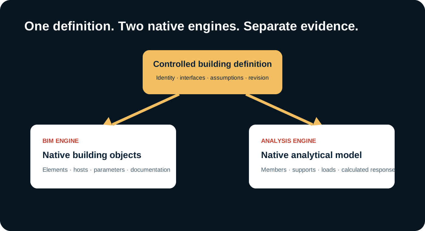
The reason is not a defect in any particular exchange format. It is that the two models are answers to different questions. A building information model describes physical objects with thickness, material, hosting, documentation, and spatial relationships. A structural analysis model describes an idealization: line and surface elements with stiffness, connectivity, restraint, and applied action. The first is a description of a thing. The second is a hypothesis about how that thing responds.
Geometry is the only part of the hypothesis that is visible in the source model. End release conditions, effective restraint, eccentricity between a member’s physical centroid and its analytical work line, the stiffness credited to a connection, whether a floor acts as a diaphragm, whether a base is pinned or has meaningful rotational restraint — none of these are properties of the physical geometry. They are decisions. When a transfer “works,” what it has moved is the part that was never in dispute.
So the design problem for the workflow is not export fidelity. It is: how do we record which physical thing became which analytical thing, under which assumptions, at which revision, so that a later reader can reconstruct the argument?
Identity mapping is the contract
The load-bearing artifact in a controlled BIM-to-analysis workflow is not the exchange file. It is the correspondence record: an explicit, stored, revision-keyed statement of which source elements map to which analytical entities, and in what cardinality.
That cardinality is rarely one-to-one, and pretending otherwise is where most drift originates.
- One to one. A single physical member becomes a single analytical member. The easy case, and the one everybody designs the workflow around.
- One to many. A continuous physical beam is split into several analytical members at intersecting nodes, load discontinuities, or section changes. The physical object still has one identity; the analytical result now exists in pieces that have to be reassembled before anyone can talk about “that beam.”
- Many to one. Several collinear physical components — segments of a wall line, stacked studs, spliced sections — are idealized as one analytical element. Any result reported against that element has to be redistributed carefully before it means anything about a specific physical piece.
- Zero to one. Analytical entities exist with no physical counterpart at all: rigid links representing offsets, fictitious supports standing in for adjacent structure outside the model, restraint elements representing a bracing system designed elsewhere. These are pure judgment and are invisible in the physical model.
- One to zero. Physical elements deliberately excluded from the analytical model — non-structural partitions, finishes, equipment — which nonetheless usually reappear as applied load. Excluding an element as stiffness while including it as mass or load is correct and routine; leaving that decision unwritten is not.
When the correspondence is stored rather than inferred, several otherwise unanswerable questions become answerable. Which physical component does this utilization ratio describe? Did this member disappear from the analytical model or was it deliberately excluded? When the source revision changed, which analytical entities became stale? Without a stored correspondence, a team can observe that two models differ but cannot explain why, which turns a technical question into an argument about whose file is newer.
Idealization is reserved judgment, not a translation setting
Exchange tools offer defaults for many of the decisions listed below. Defaults are a convenience, not an authority. Each of these is a claim about physical behavior, and each belongs to the engineer of record rather than to a mapping table:
- End conditions and releases. Whether a connection is treated as pinned, fixed, or partially restrained, and what that assumption implies for the connection detail that must eventually be designed and built.
- Work lines and eccentricity. Whether a member’s analytical line coincides with its physical centroid, and whether the resulting offset is modeled, absorbed, or explicitly neglected.
- Diaphragm behavior. Whether a floor or roof assembly is rigid, semi-rigid, or flexible for the distribution of lateral action — a choice with large consequences in light-gauge and panelized construction, where the assumption depends on sheathing, fastening, and openings rather than on the slab-like appearance of a model element.
- Base restraint. Whether an anchorage is idealized as pinned or as providing rotational stiffness, and whether the foundation and the soil below it are represented, replaced by a support, or excluded entirely.
- Effective length and bracing. Which points are credited as braced, by what, and whether that bracing exists in the analytical model, in a separate design, or only in the detailer’s intent.
- Stiffness of what is not modelled. Partitions, cladding, and finishes usually contribute stiffness that is deliberately ignored. Ignoring it is conservative in some checks and unconservative in others.
This is the class of work the series hub calls reserved judgment: work that produces an acceptance criterion rather than satisfying one. Automation can carry these decisions faithfully, apply them consistently, and report where a default was used instead of an explicit choice. It cannot make them, because the missing ingredient is professional standing, not processing capability.
The load boundary has to be declared, because geometry does not contain it
A second and equally common failure is treating loading as something that can be derived from the model. Part of it can. Most of it cannot.
Geometry can supply member self-weight, once section and material are assigned, and the tributary areas implied by the arrangement. That is close to the whole of what the physical model knows about load.
The engineer must declare superimposed dead load from the actual assembly build-up; live load by occupancy and its reduction rules; environmental actions derived from the site rather than the drawing — wind exposure and topography, ground snow and its accumulation, seismic parameters and site classification; thermal and shrinkage effects where relevant; and the combinations under which all of these are checked. None of these are geometric facts. They are project facts, tied to a specific property and a specific code edition, and they change when the site changes even if the building does not.
And the boundary itself must be stated — the place where the analytical model stops and something else takes over. Common boundaries in a panelized residential frame include the anchorage interface at the foundation, where soil-structure interaction and foundation design are separate work; connection design delegated to a fabricator or a specialty engineer; and the transient conditions — lifting, transport, temporary bracing, partially erected states — which govern components more often than people expect and which appear nowhere in an in-service model.
Writing the boundary down converts a silent gap into a visible scope item. A model that quietly ends at the base plate is not wrong. A model that quietly ends at the base plate and is then described as “the structural model for the building” is a misunderstanding waiting to be discovered by whoever designs the foundation.
Read both engines back, and compare against the mapping
Once a run completes, the useful question is not whether it succeeded. It is what each environment now contains, expressed in that environment’s own vocabulary, so the two can be checked against the correspondence record rather than against each other’s screenshots.
From the BIM side, the workflow should retrieve the native element inventory by category and level, host relationships for anything hosted, type and parameter state for the properties that matter, the mapping keys that tie elements to their analytical counterparts, and the revision under which all of this exists.
From the analysis side, the workflow should retrieve the model that was actually solved: node and member inventory, the support inventory and its restraint conditions, releases as applied rather than as requested, the load cases and combinations that were actually run, the applied load totals per case, solver warnings, any instability or singularity reported, and any case that did not solve.
The comparison then asks questions that neither engine can answer alone. Does every mapped physical element have a live analytical counterpart, and vice versa? Do the applied load totals reconcile with the declared basis — does the sum of applied vertical action match what the declared build-up and areas imply, within an explicable difference? Were the releases the engineer specified the releases the solver used, or did an import default overwrite them? Did any member silently acquire or lose a support? Does the revision that produced the analytical model match the revision that produced the BIM model, or has one moved?
That last check catches more real problems than the sophisticated ones. It is also the check most often skipped, because both files open without complaint.
The mechanics of retrieving this kind of structured evidence from a native authoring environment — rather than inferring it from a view or an export — are covered in our report on native Revit models and readback.
A solved model is not an engineering conclusion
This deserves its own statement, because a completed structural run is one of the most persuasive-looking artifacts in the industry and one of the weakest as evidence of building adequacy.
Solver completion is a property of the numerical problem. It says the assembled system was solvable and that the software found a solution to the equations it was given. It is entirely compatible with:
- a member that is not in the model at all, so nothing about it was checked;
- an idealization that does not match how the assembly will actually be built and connected;
- a load case that was declared but never applied, or applied to the wrong surfaces;
- a support that stabilizes the model numerically while representing restraint that does not exist on site;
- a source revision superseded before the run finished;
- a code check performed against provisions that do not govern this project;
- utilization ratios below unity that are correct for the model and irrelevant to the building.
None of those conditions produces an error. Several of them produce a cleaner result than the correct model would.
Turning a run into an engineering conclusion requires additions that no solver supplies: the assumptions written where a reviewer can inspect them, the scope of what was and was not checked, reconciliation of results back through the correspondence record to physical components, review by the responsible professional, and the professional’s own acceptance of the outcome. The certification, seal, and responsibility belong to a licensed engineer working under the applicable code and jurisdiction. A workflow’s job is to make that person’s review faster and better-informed — never to look like a substitute for it. Our project roles page describes how those responsibilities are assigned on a project.
The distinction to hold onto. “The analysis completed” is a statement about software. “The structure is adequate” is a statement about a building, made by a person who is accountable for it. A workflow that lets the first sentence stand in for the second has automated the wrong thing.
Coming back: results belong in the record, not in the geometry
The return path is where well-run workflows most often lose their discipline. An analysis produces section changes, and the fastest way to reflect them is to edit the analytical model and re-export, or to edit the BIM model directly and hope the two stay aligned. Both shortcuts break the correspondence, because the change now originates in a place that is not the controlled definition.
The rule that keeps the loop honest is that changes travel through the definition. An engineering result proposes a change; the change is authorized against the shared definition at a stated revision; both engine models are regenerated or updated from that revision; and both are read back to confirm they now agree with it. Results themselves — ratios, reactions, deflections, governing cases — belong in the project record attached to the revision that produced them. They are evidence about a state, not an authority over geometry.
This matters most when the change is small enough to feel harmless. Adjusting one section changes self-weight, may change the connection that was already detailed, may change the panel it sits in, and may change a fabrication release that has already gone out. Which of those consequences apply is a relationship question rather than a structural one, and it is the subject of the companion report on design change in a repeatable housing product.
What a defensible handoff record has to answer
- Which source revision produced the BIM model, and which produced the analytical model?
- Which physical elements map to which analytical entities, in what cardinality, and which elements were deliberately excluded?
- Which idealization decisions were made explicitly, and which were inherited from a translation default?
- What is the declared load basis, and what does the analytical boundary exclude?
- What did each engine actually contain and actually solve, as reported by that engine?
- Do the applied load totals reconcile with the declared basis?
- What changed since the last accepted state, and which prior results are now stale?
- Who is the responsible professional, what did their review cover, and what did it not cover?
A workflow that can answer these eight questions can defend its results. A workflow that cannot is relying on the fact that nobody has asked yet.
Why this matters for panelized residential structures
The BIM-to-analysis boundary is more consequential in repeatable, panelized construction than in one-off design, for two reasons. First, idealization is genuinely harder: light-gauge steel assemblies behave as systems, and the assumptions about sheathing, fastening, and openings that govern their behavior are not visible as geometry. Second, a mistake in a repeated assembly is a mistake reproduced, not a mistake encountered.
That is why K&K treats the correspondence record, the declared load basis, and dual-engine readback as part of the deliverable rather than as internal housekeeping. K&K coordinates design and delivery interfaces with the required project professionals, and licensed roles remain jurisdiction-specific. Related research on the connection between design geometry, structure, and downstream production decisions is described in our floor-plan-to-steel-frame research note and our broader technology and R&D program.
Public boundary
This report describes an information-control and evidence method at a conceptual level. It is not a structural design, a capacity statement, a sealed calculation, a code-compliance opinion, or an approval of any particular building. It publishes no released engineering parameters, product data, or project-specific results.
Project-specific structural engineering remains the responsibility of the licensed professionals engaged for that project, under the applicable codes, site conditions, supplier information, and authorities having jurisdiction. See our compliance and project-record approach for the documentation boundary, or contact us to discuss a specific residential project and its property conditions.