
Data Center One-Line Diagram: Real 12.47 kV Examples You Can Download
Most “data center single-line diagram” results are gated vendor whitepapers or stripped-down block diagrams. This page explains what a real data center one-line contains and links to a free 88-page electrical drawing book — actual engineering sheets from a GB300-class GPU facility design, direct download, no registration.
What a One-Line Diagram Shows in a Data Center
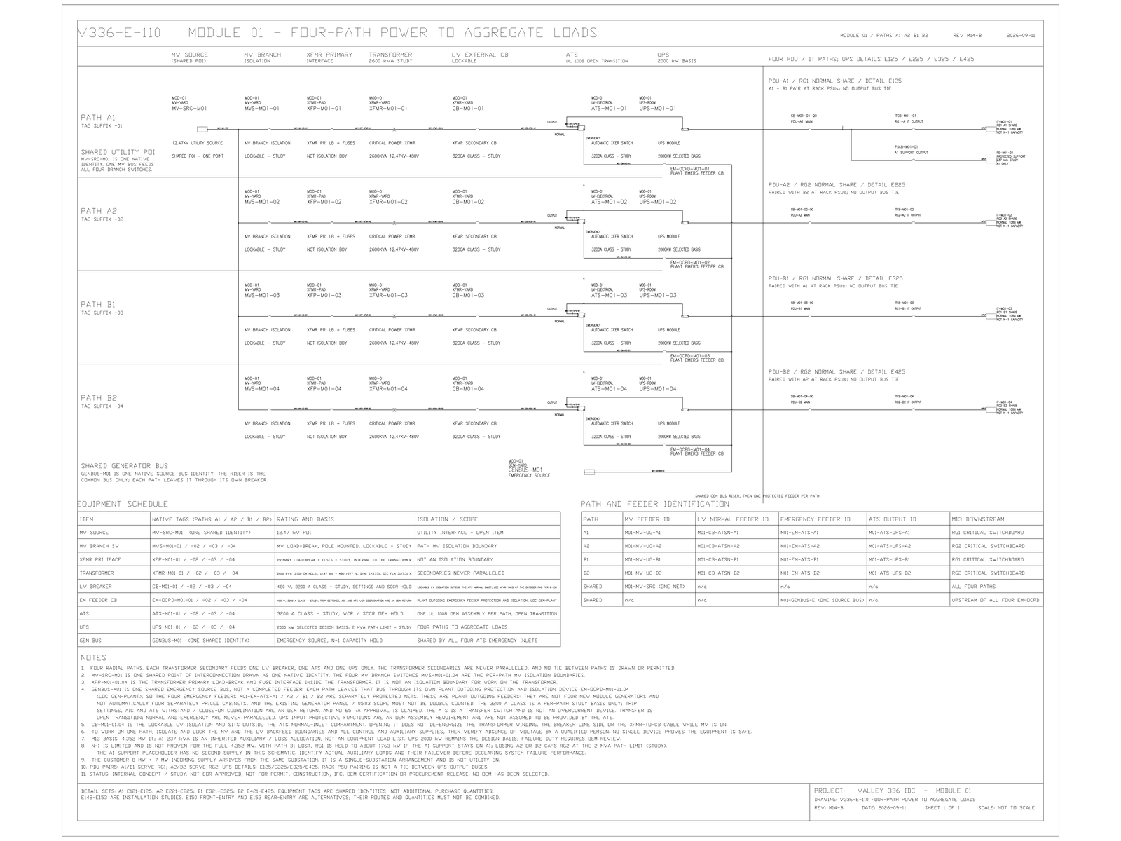
A one-line diagram — the same document many engineers call a single-line diagram — is the master map of a facility’s electrical system. Each circuit is drawn as one line regardless of how many phase conductors it carries, so a single sheet can show the whole chain from the utility service entrance to the rack: medium-voltage switching, transformers, low-voltage switchgear, automatic transfer switches (ATS), UPS blocks, and the power distribution units (PDUs) that feed IT loads — together with the ratings of the protective devices between them. It is the first drawing a utility, a lender’s engineer, or a commissioning agent asks for, because it exposes the failure domains: what trips together, what transfers, and what rides through.
The Example Set: 12.47 kV Service to 136 kW GPU Racks
The one-line diagrams on this site come from a coordinated GB300-class GPU facility design. The chain on the zone one-lines runs: loadbreak switch → fused primary → 2500 kVA transformer (12.47 kV to 480Y/277 V) → secondary breaker → ATS → 2 MW UPS → PDU → a 42-rack GPU zone at 136 kW per rack. The set covers both six-path and four-path radial distribution variants, generator feeder interfaces, grounding, and buried-utility crossing details. The figure above is sheet V336-E-110, the four-path power one-line from a shared utility point of interconnection down to the PDU paths.
One-Line, Single-Line, Riser, Block Diagram
The terminology overlaps and search engines treat the terms differently, so to be plain: one-line diagram and single-line diagram are the same document. A riser diagram shows vertical distribution through a multi-story building. A block diagram is the simplified marketing version — boxes and arrows without device ratings — and is not an engineering document. What you can download here are one-lines in the engineering sense: device ratings, transfer logic and interface points on the sheet.
How to Read the Sheets
The 88-page electrical drawing book is organized as an E-100 distribution series and an E-300 detail series. Every sheet states its own assumptions and open items, and the set is published at Design Development — Public Edition status: real working drawings for study and evaluation, not construction issues. The wider engineering reasoning behind the architecture — failure domains, UPS sizing, feeder protection — is documented in the electrical architecture cluster of the Data Center Lab.
Download the Drawing Set
Every document is a direct PDF download — no registration, no email gate — with a published SHA-256 checksum on the downloads page:
- Electrical Drawing Book — PE-P1 (14 MB, 88 pages)
- Structural Document Set — Public Edition P1 (84 MB, 170 pages)
- GPU Hall Network Reference Design — PE-P1 (1.5 MB, 58 pages)
- All Three Disciplines — Combined ZIP (97 MB, 3 documents)
Published at Design Development — Public Edition P1 status: reference designs for study and evaluation, not construction issues, not sealed by an Engineer of Record. Reuse follows the attribution terms stated inside each document.
Common Questions
Is a one-line diagram the same as a single-line diagram?
Yes. One-line diagram and single-line diagram are two names for the same document: each circuit drawn as a single line with device ratings, regardless of the number of phase conductors. This drawing set uses both terms interchangeably.
What voltage levels does the example use?
12.47 kV medium-voltage utility service, stepped down through 2500 kVA transformers to 480Y/277 V for distribution to ATS, UPS and PDU paths feeding 42-rack GPU zones at 136 kW per rack.
Why does the design use four separate power paths?
Each path carries its own transformer, ATS and 2 MW UPS block, so a fault or maintenance action on one path is contained to that path. The four-path and six-path zone one-lines in the set show how the paths divide the 42-rack zone load.
Can I reuse these one-line diagrams in my own project?
They are published for study and evaluation at Design Development — Public Edition status: not construction issues, not sealed by an Engineer of Record. Reuse follows the copyright and attribution terms stated inside each document, and every interface must be verified against your own utility and equipment data.
Questions about any sheet or parameter: inquiry@kkdatasvc.com or the contact page.