
Data Center Lab · Reference Designs · Electrical
Sheet E-108: Zone 8 One-Line Diagram — Seven UPS Paths to a 48-Rack Hall
Seven radial paths leave one 8 MW, 12.47 kV breaker, and the sheet's IT note gives the end UPS paths a different kilowatt duty than the paths between them.
Design Development — Public Edition P1: a reference design for study and evaluation, not a construction issue, not sealed by an Engineer of Record.
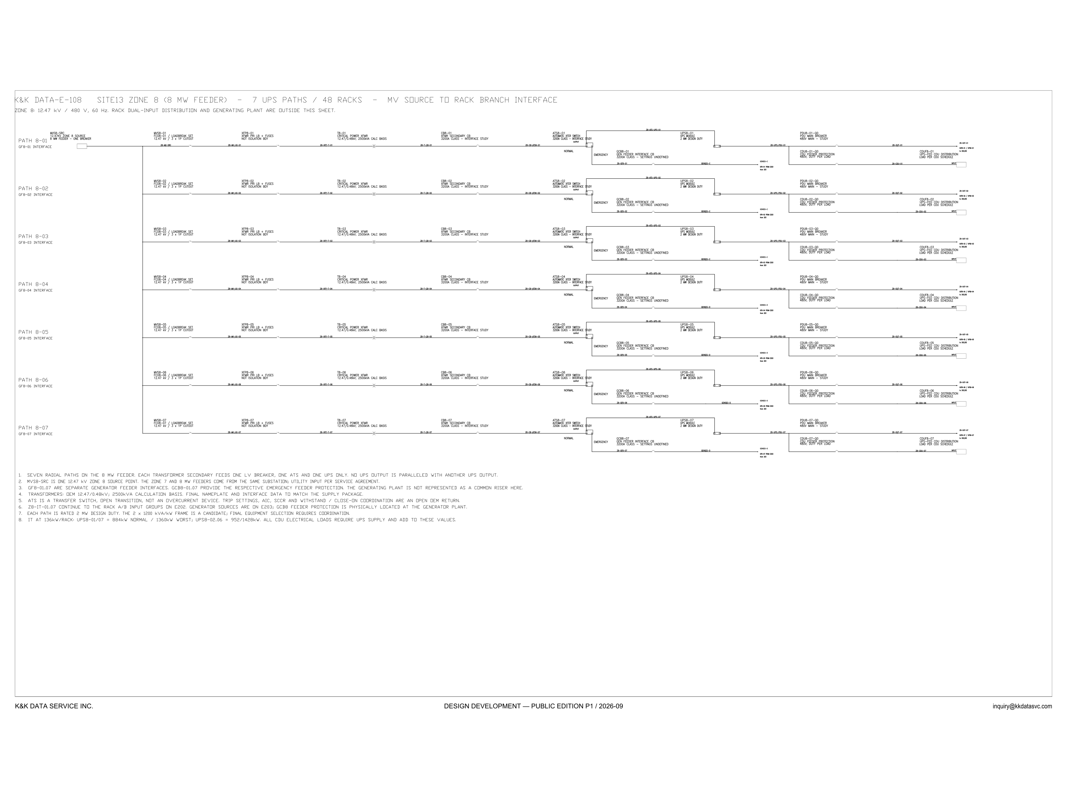
Scroll or pinch to zoom, drag to pan, click a highlighted device for its explanation. Vector drawing — it stays sharp at any magnification.
← E-107 · All electrical sheets · E201 →
What this sheet shows
E-108 draws the power chain of Zone 8 at one-line depth, on the SITE13 sheet titled for an 8 MW feeder, 7 UPS paths and 48 racks. The subtitle fixes the basis: 12.47 kV / 480 V, 60 Hz, and it says rack dual-input distribution and the generating plant are outside this sheet. MVS8-SRC is one 12.47 kV zone source point, one breaker. Seven radial paths, PATH 8-01 through PATH 8-07, leave that bus: loadbreak set and 3 × 1P cutout (MVS8 / FCO8) → primary fuses (XFP8) → critical-power transformer (T8) → secondary breaker (CB8) → automatic transfer switch (ATS8) → UPS module → 480 V PDU main, with a UPS-fed CDU branch and a rack-branch tag 2R-IT. Each row is also labeled as a GF8 interface. The generator breaker itself sits on the ATS emergency side.
Design intent you can read off the sheet
The general notes put the architecture in words. Seven radial paths are on the 8 MW feeder, and each transformer secondary feeds one low-voltage breaker, one ATS and one UPS only. No UPS output is paralleled with another UPS output. The ATS is a transfer switch, open transition, and not an overcurrent device. Each path is rated 2 MW design duty. A 2 × 1200 kVA/kW frame is named as a candidate, and final equipment selection requires coordination. GF8-01 through GF8-07 are separate generator feeder interfaces. GCB8-01 through GCB8-07 provide the emergency feeder protection on each path. The generating plant is not represented as a common riser. The Zone 7 and 8 MW feeders come from the same substation, and the utility input is per the service agreement. Keeping the UPS outputs unparalleled, with a separate generator interface on every path, is the failure-domain choice this sheet draws. The same question is discussed in the electrical architecture notes.
Two IT duties on one repeated path
The equipment chain is drawn the same seven times. The IT line is not. It prints 136 kW per rack, then UPS8-01/07 as 884 kW normal and 1360 kW worst, and UPS8-02:06 as 952/1428 kW. Read with those marks, the two end modules UPS8-01 and UPS8-07 carry the first pair, and UPS8-02 through UPS8-06 carry the second. All CDU electrical loads require UPS supply and add to these values, so a CDU kilowatt is not inside 884 or 952. The CDU blocks themselves say duty per load and load per the CDU schedule, and this sheet states no CDU kilowatt. The 2 MW on the UPS block is the path design duty, a different number from either IT pair, and the 2 × 1200 kVA/kW frame is still only a candidate. Rack A/B input groups, where the two duties would be carried rack by rack, continue on E202. A reader who gives every Zone 8 UPS the 952 kW figure has skipped the end paths.
Status
Published at Design Development — Public Edition P1 (title block: 2026-09): a reference design for study and evaluation, not a construction issue, carrying its open items on the symbols and in the notes. Each transformer is an OEM 12.47/0.48 kV unit on a 2500 kVA calculation basis, and final nameplate and interface data are to match the supply package. The secondary breaker and the ATS are marked interface study, 3200 A class. Trip settings, AIC, SCCR and withstand / close-on coordination are an open OEM return. The generator feeder breaker is 3200 A class with settings undefined, and the notes place that protection physically at the generator plant, with generator sources on E203. The PDU main is marked study.
Sheet guide — the devices on this drawing
MVS8-01 — 12.47 kV loadbreak set and cutout
Each path taps the zone bus through its own loadbreak set. On this row the block reads MVS8-01 and FCO8-01, 12.47 kV, 3 × 1P cutout. MVS8-SRC, above the bus, is the single Zone 8 source: one breaker on the 8 MW feeder. The same cutout repeats on the paths below.
XFP8-01 — transformer primary fuses
Primary fuses ahead of the critical-power transformer, tagged XFP8-01. The block is marked not an isolation boundary, so this fuse is not the isolation point of the path. The same fuse block is repeated on each of the seven paths.
T8-01 — 2500 kVA transformer, 12.47/0.48 kV
Critical-power transformer T8-01, 12.47/0.48 kV, on a 2500 kVA calculation basis. The note says final nameplate and interface data are to match the supply package, so 2500 kVA is the study basis and not a closed nameplate. T8-02 through T8-07 are drawn the same way.
CB8-01 — 3200 A secondary breaker
Transformer secondary breaker CB8-01, 3200 A class, marked interface study. The notes leave trip settings, AIC, SCCR and withstand/close-on coordination as an open OEM return. Each transformer secondary feeds this one breaker, not a shared low-voltage board.
ATS8-01 — automatic transfer switch
Open-transition automatic transfer switch ATS8-01, between the normal source and the emergency source. The notes say it is a transfer switch and not an overcurrent device. The block is marked 3200 A class, interface study. Normal is the utility path; emergency is the generator feeder.
GCB8-01 — generator feeder interface breaker
Generator feeder interface breaker GCB8-01, 3200 A class, settings undefined. The notes call GCB8-01 through GCB8-07 the emergency feeder protection, and they place that protection physically at the generator plant. Generator sources are on E203. The plant is not drawn here as a common riser.
UPS8-01 — 2 MW UPS module
One UPS module on this path, UPS8-01, marked 2 MW design duty. The notes name a 2 × 1200 kVA/kW frame as a candidate and say final selection requires coordination. The output is not paralleled with another UPS. The IT kilowatts in the notes are a separate figure, and they are not the same on every path.
PDU8-01 — 480 V PDU main and rack branch
The 480 V PDU main breaker, PDU8-01, is marked study. Past it, this row continues as rack branch 2R-IT-01. The notes send 2R-IT-01 through 2R-IT-07 on to the rack A/B input groups on E202. Rack dual-input distribution is outside this sheet.
CDU8-01 — UPS-fed CDU distribution
A branch from the UPS output feeds CDU protection at 480 V, duty per load, and the UPS-fed CDU distribution CDU8-01, load per the CDU schedule. The IT note says all CDU electrical loads require UPS supply and add to the path IT figures. No CDU kilowatt is printed on this sheet.
General notes — path duty and open items
Seven radial paths on one feeder; one low-voltage breaker, one ATS and one UPS per transformer secondary; UPS outputs unparalleled. IT basis 136 kW per rack, with UPS8-01 and UPS8-07 at 884 kW normal and 1360 kW worst, and UPS8-02 through UPS8-06 at 952/1428 kW. Nameplate, trip settings and final equipment selection are left open in these same notes.
Get the full drawing set
This sheet is one page of the Electrical Drawing Book — Public Edition P1 (88 pages, 14 MB) — a direct PDF download with a published SHA-256 checksum, no registration. The complete coordinated set is on the downloads page. Background guides: data center one-line diagrams · GB300 NVL72 facility requirements · liquid cooling and CDU design.
Questions about any device or parameter on this sheet: inquiry@kkdatasvc.com or the contact page.