
Data Center Lab · Reference Designs · Electrical
Sheet E-107: Zone 7 One-Line Diagram — Six UPS Paths to a 42-Rack GPU Hall
Six radial paths from one 12.47 kV zone source to the rack branch interface — the whole power chain of a 42-rack, 136 kW/rack GPU hall on one sheet.
Design Development — Public Edition P1: a reference design for study and evaluation, not a construction issue, not sealed by an Engineer of Record.
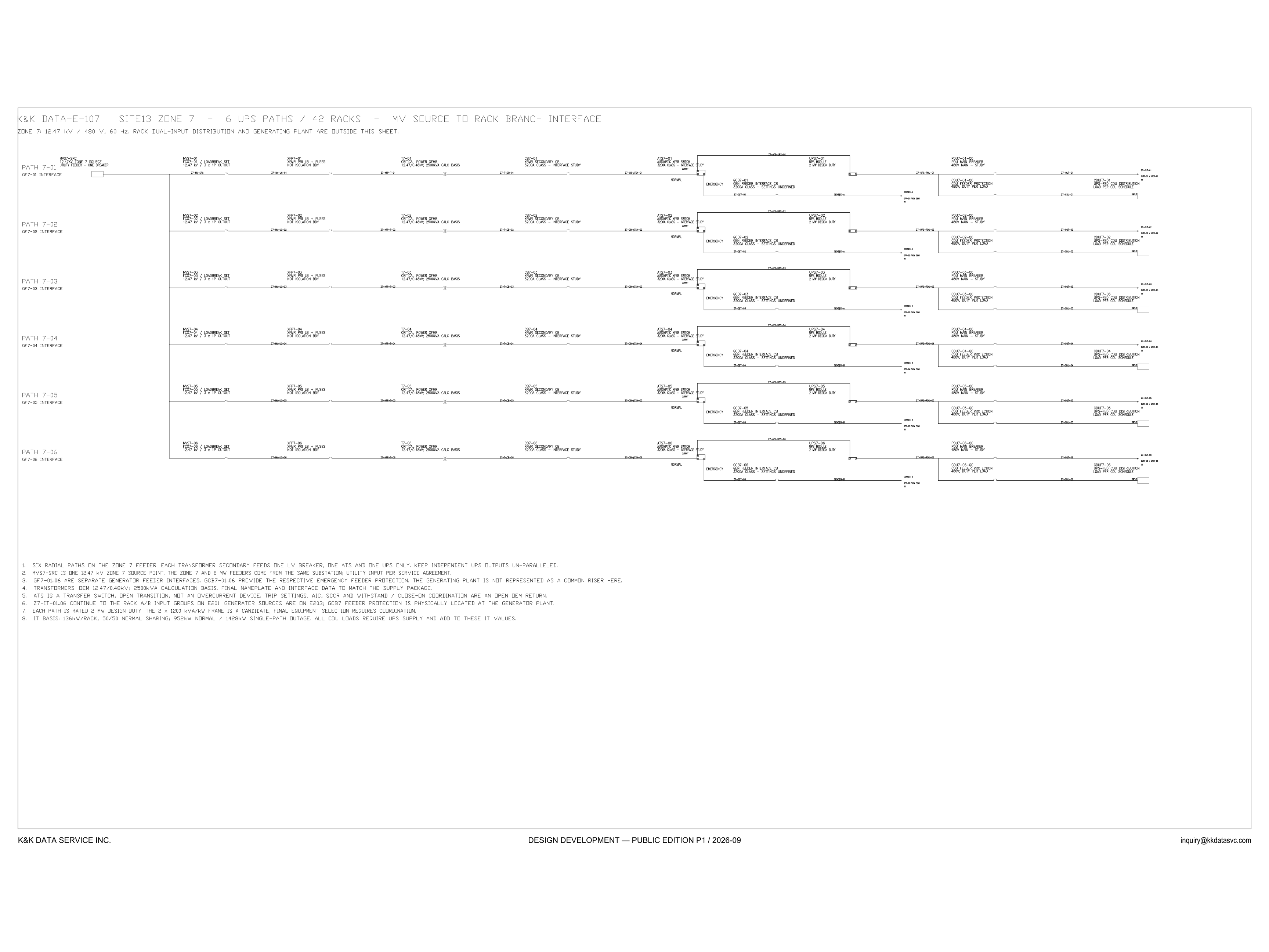
Scroll or pinch to zoom, drag to pan, click a highlighted device for its explanation. Vector drawing — it stays sharp at any magnification.
← E-106 · All electrical sheets · E-108 →
What this sheet shows
E-107 draws the complete power chain of GPU hall Zone 7 at one-line depth: a single 12.47 kV zone source point (MVS7-SRC, one utility breaker) feeding six independent radial paths, PATH 7-01 through 7-06. Each path runs loadbreak set and fused cutout → primary fuses → 2500 kVA critical-power transformer (12.47 kV to 480 V) → 3200 A-class secondary breaker → automatic transfer switch → 2 MW UPS module → 480 V PDU main → and a UPS-fed CDU distribution feeder for the liquid-cooling plant. Generator feeder interfaces (GCB7-01…06) enter each path at the ATS emergency side.
Design intent you can read off the sheet
The general notes carry the architecture decisions in plain text: six radial paths whose transformer secondaries each feed exactly one LV breaker, one ATS and one UPS, with independent UPS outputs kept un-paralleled; the ATS as an open-transition transfer switch, explicitly not an overcurrent device; each path rated 2 MW design duty with a 2 × 1200 kVA/kW frame as the candidate; and an IT basis of 136 kW per rack with 50/50 normal sharing — 952 kW normal and 1428 kW single-path-outage duty per path, with all CDU loads on UPS supply on top. The failure-domain reasoning behind this architecture is documented across the electrical architecture cluster.
Status
Published at Design Development — Public Edition P1 status (title block: 2026-09): a reference design for study and evaluation, not a construction issue, carrying its own assumptions and open items as sheet notes. Transformer nameplate, ATS trip settings and final equipment selection are marked as open coordination items on the sheet itself.
Sheet guide — the devices on this drawing
MVS7-01 — 12.47 kV loadbreak set + cutout
Each path taps the zone source through its own loadbreak set and 3 x 1P fused cutout at 12.47 kV. The sheet notes one utility feeder and one breaker at the zone source point; per-path protection starts here.
XFP7-01 — transformer primary fuses
Primary fuse set ahead of the critical-power transformer. Notes mark it 'not isolation boundary' — isolation and grounding duties live elsewhere in the chain.
T7-01 — 2500 kVA transformer, 12.47 kV / 480 V
OEM 12.47/0.48 kV transformer on a 2500 kVA calculation basis. The sheet flags final nameplate and interface data as items to match the supply package — an honest open item, stated on the drawing.
CB7-01 — 3200 A-class secondary breaker
Transformer secondary circuit breaker, 3200 A class, marked interface study: trip settings, AIC, SCCR and withstand/close-on coordination are an open OEM return per the general notes.
ATS7-01 — automatic transfer switch
Open-transition transfer switch between the normal (utility) and emergency (generator) sources. The notes are explicit: it is a transfer switch, not an overcurrent device — protection lives in the breakers around it.
GCB7-01 — generator feeder interface
Each path has a separate generator feeder interface with its own emergency feeder protection (3200 A class, settings undefined at this stage). The generating plant itself is outside this sheet — and is not drawn as a common riser.
UPS7-01 — 2 MW UPS module
One UPS module per path at 2 MW design duty, candidate frame 2 x 1200 kVA/kW. Independent UPS outputs are kept un-paralleled by design — a failure-domain decision the Lab's UPS cluster analyses in depth.
PDU7-01 — 480 V PDU main breaker
The path's 480 V PDU main — the last distribution stage before the rack branch interface. Rack dual-input (A/B) grouping continues on sheet E-201.
CDU7-01 — UPS-fed CDU distribution
Liquid-cooling CDU feeder protection and distribution, fed from the UPS side: per the IT-basis note, all CDU loads require UPS supply and add on top of the 136 kW/rack IT values. The cooling plant rides through with the compute.
General notes 1–8 — the architecture in text
Six radial paths; one LV breaker + one ATS + one UPS per transformer secondary; UPS outputs un-paralleled; ATS open transition; 2 MW path duty; IT basis 136 kW/rack, 50/50 sharing, 952 kW normal / 1428 kW single-path outage. The design intent is stated on the sheet, not hidden in a calc file.
Get the full drawing set
This sheet is one page of the Electrical Drawing Book — Public Edition P1 (88 pages, 14 MB) — a direct PDF download with a published SHA-256 checksum, no registration. The complete coordinated set is on the downloads page. Background guides: data center one-line diagrams · GB300 NVL72 facility requirements · liquid cooling and CDU design.
Questions about any device or parameter on this sheet: inquiry@kkdatasvc.com or the contact page.