
Data Center Lab · Reference Designs · Electrical
Sheet E-106: One Typical Medium-Voltage Branch from the Zone Trunk to the OEM Transformer
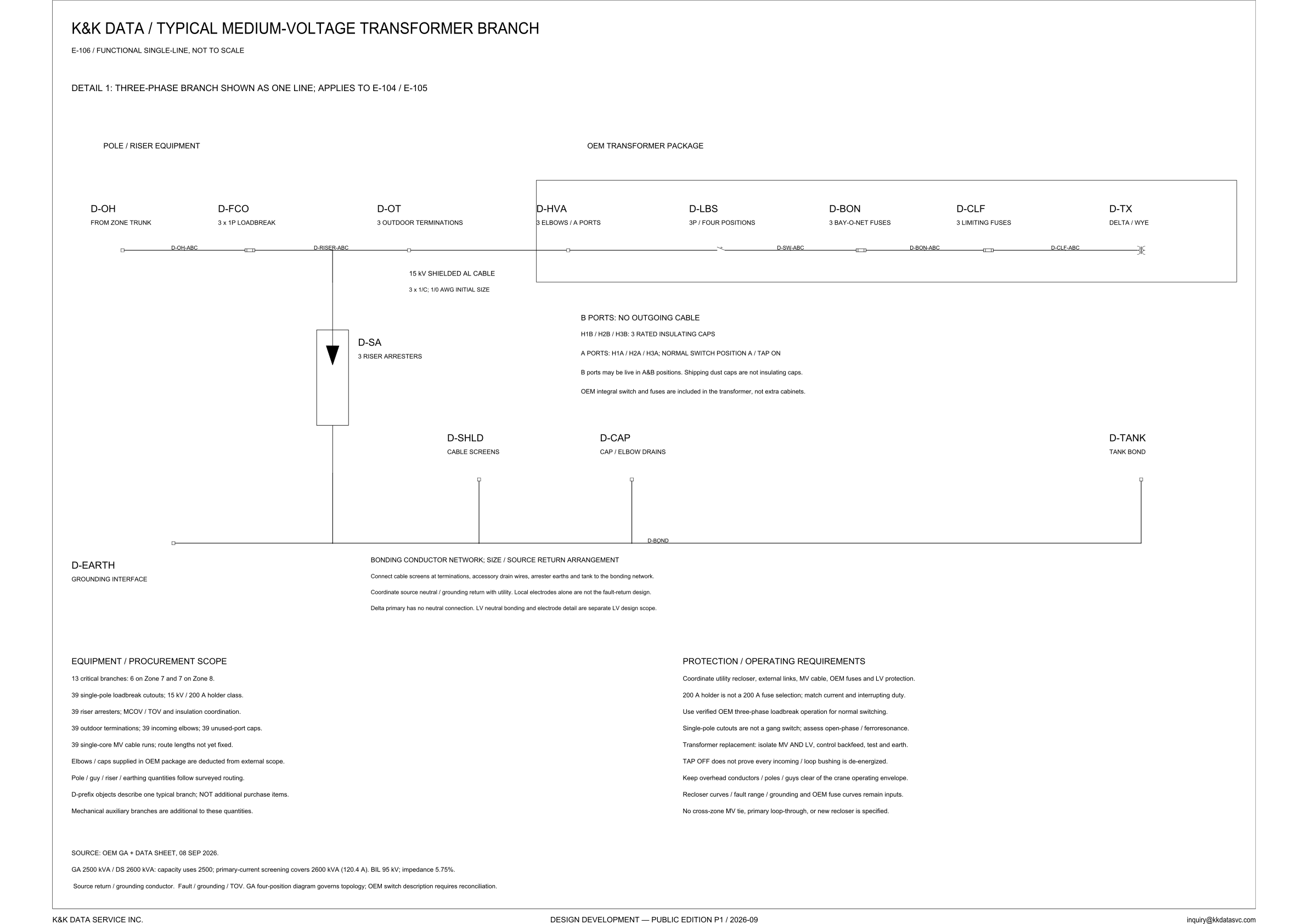
One not-to-scale line is the typical branch Detail 1 applies to E-104 and E-105: the pole equipment, the OEM package, and a note that the D-prefix tags are not additional purchase items.
Design Development — Public Edition P1: a reference design for study and evaluation, not a construction issue, not sealed by an Engineer of Record.
Scroll or pinch to zoom, drag to pan, click a highlighted device for its explanation. Vector drawing — it stays sharp at any magnification.
← E-105 · All electrical sheets · E-107 →
What this sheet shows
E-106 is a functional single-line, marked not to scale. Detail 1 says the three-phase branch is shown as one line, and that the detail applies to E-104 and E-105. The sheet divides the branch into pole / riser equipment and the OEM transformer package. From the zone trunk the line runs D-OH, then D-FCO, drawn as 3 × 1P loadbreak, then D-OT, three outdoor terminations. The cable callout on that run reads 15 kV shielded aluminum, 3 × 1/C, with 1/0 AWG as the initial size. Segment tags on this side of the package are D-OH-ABC and D-RISER-ABC. A leg drops off that run to D-SA, three riser arresters. Inside the package the line continues D-HVA, three elbows on the A ports, D-LBS, a 3P switch of four positions, D-BON, three bay-o-net fuses, D-CLF, three limiting fuses, and D-TX, marked delta / wye. Segment tags inside the box read D-SW-ABC, D-BON-ABC, and D-CLF-ABC.
Ports, caps, and the bonding network
The note under the package is the switch as operated. A ports are H1A / H2A / H3A, and the normal position printed there is A / tap on. B ports are H1B / H2B / H3B, with no outgoing cable, and that line gives them three rated insulating caps. B ports may be live in A&B positions. Shipping dust caps are not insulating caps. The same note says the OEM integral switch and fuses are included in the transformer, not extra cabinets. Below the one-line, D-SHLD (cable screens), D-CAP (cap / elbow drains), and D-TANK (tank bond) drop to the bonding conductor D-BOND. D-EARTH is the grounding interface on that conductor. The bonding note says to connect cable screens at terminations, accessory drain wires, arrester earths, and the tank to the bonding network. Source neutral and grounding return are to be coordinated with the utility. Local electrodes alone are not the fault-return design. The delta primary has no neutral connection, and LV neutral bonding and electrode detail are separate LV design scope.
Thirteen branches, and what the 200 A figure is
The equipment block states the population this one line stands for: 13 critical branches, 6 on Zone 7 and 7 on Zone 8. Printed with that statement are 39 single-pole loadbreak cutouts, 15 kV / 200 A holder class; 39 riser arresters, with MCOV / TOV and insulation coordination named beside them; 39 outdoor terminations, 39 incoming elbows, and 39 unused-port caps; and 39 single-core MV cable runs, with route lengths not yet fixed. The cutout on the one-line is drawn 3 × 1P, and the equipment block counts 39 single-pole loadbreak cutouts. Elbows and caps supplied in the OEM package are deducted from external scope. Pole, guy, riser, and earthing quantities follow surveyed routing. D-prefix objects describe one typical branch and are not additional purchase items. Mechanical auxiliary branches are additional to these quantities. The protection block says the 200 A holder is not a 200 A fuse selection, and says to match current and interrupting duty. It says to use verified OEM three-phase loadbreak operation for normal switching, and that single-pole cutouts are not a gang switch, so open-phase / ferroresonance is to be assessed. Utility recloser, external links, MV cable, OEM fuses, and LV protection are named as one coordination. For transformer replacement the sheet says to isolate MV and LV, control backfeed, test and earth. TAP OFF does not prove every incoming / loop bushing is de-energized. Overhead conductors, poles, and guys are to be kept clear of the crane operating envelope. Recloser curves, fault range, grounding, and OEM fuse curves remain inputs. No cross-zone MV tie, primary loop-through, or new recloser is specified. The same boundary question is taken up in the electrical architecture notes.
Status
Published at Design Development — Public Edition P1 (title block: 2026-09): a reference design for study and evaluation, not a construction issue. The source line cites the OEM general arrangement and data sheet of 08 SEP 2026. It prints GA 2500 kVA / DS 2600 kVA, and then which figure is used for what: capacity uses 2500, and primary-current screening covers 2600 kVA (120.4 A). The same line prints BIL 95 kV and impedance 5.75%. The cable on the one-line is an initial size. Route lengths of the single-core runs are not yet fixed. Under that citation the sheet lists source return / grounding conductor and fault / grounding / TOV, says the GA four-position diagram governs topology, and says the OEM switch description requires reconciliation. Recloser curves, fault range, grounding, and OEM fuse curves remain inputs. The equipment scope prints 15 kV / 200 A holder class with the 39 single-pole loadbreak cutouts, and the protection note says the 200 A holder is not a 200 A fuse selection.
Sheet guide — the devices on this drawing
D-OH, D-FCO, D-OT — trunk, cutout, terminations
Pole and riser side of the typical branch. D-OH is the tap from the zone trunk, D-FCO is the 3 x 1P loadbreak, and D-OT is three outdoor terminations. The cable callout reads 15 kV shielded aluminum, 3 x 1/C, with 1/0 AWG as the initial size. Segment tags on this run are D-OH-ABC and D-RISER-ABC.
D-SA — 3 riser arresters
D-SA is three riser arresters on the leg that drops off the branch. The procurement block counts 39 riser arresters for the critical branches and names MCOV / TOV and insulation coordination beside that count. The bonding note includes arrester earths among the connections brought to the bonding network.
D-HVA, D-LBS — elbows and the four-position switch
D-HVA is three elbows on the A ports, and D-LBS is the 3P switch of four positions, with the segment tagged D-SW-ABC. Normal position is A / tap on at H1A, H2A, and H3A. B ports H1B, H2B, and H3B have no outgoing cable and are shown with three rated insulating caps; they may be live in A&B positions, and shipping dust caps are not those insulating caps. The integral switch and fuses are included in the transformer, not extra cabinets.
D-BON, D-CLF, D-TX — fuses and delta/wye
D-BON is three bay-o-net fuses and D-CLF is three limiting fuses, tagged D-BON-ABC and D-CLF-ABC on the segments ahead of D-TX. D-TX is marked delta / wye. The note under the ports says these integral fuses are included in the transformer, not extra cabinets.
D-SHLD, D-CAP, D-TANK — screens, drains, tank bond
Three bonds leave the branch for the bonding conductor. D-SHLD is the cable screens, D-CAP is the cap and elbow drains, and D-TANK is the tank bond. The bonding note names cable screens at terminations, accessory drain wires, and the tank together as connections into that network.
D-EARTH — grounding interface and bonding note
D-EARTH is the grounding interface at the left end of the bonding conductor. Left to right, the riser-arrester earth under D-SA, D-SHLD, D-CAP, and D-TANK land on that conductor at separate taps. The D-BOND tag is on the right-hand run beside the D-CAP tap. The note says to coordinate source neutral and grounding return with the utility, and that local electrodes alone are not the fault-return design. The delta primary has no neutral connection, and LV neutral bonding and electrode detail are separate LV design scope.
Equipment scope — 13 branches and the 39-counts
The procurement block gives the population this one line stands for: 13 critical branches, 6 on Zone 7 and 7 on Zone 8. It counts 39 single-pole loadbreak cutouts at a 15 kV / 200 A holder class, 39 riser arresters, 39 outdoor terminations, 39 incoming elbows, 39 unused-port caps, and 39 single-core MV cable runs, and it says the route lengths are not yet fixed. Elbows and caps supplied in the OEM package are deducted from external scope; D-prefix objects describe one typical branch and are not additional purchase items; mechanical auxiliary branches are additional to these quantities; and pole, guy, riser, and earthing quantities follow surveyed routing.
Protection requirements — holder, switching, no tie specified
The block says to coordinate the utility recloser, external links, MV cable, OEM fuses, and LV protection, and that the 200 A holder is not a 200 A fuse selection: match current and interrupting duty. Normal switching is to use verified OEM three-phase loadbreak operation; single-pole cutouts are not a gang switch, so open-phase and ferroresonance are to be assessed, and TAP OFF does not prove every incoming or loop bushing is de-energized. Replacement is isolate MV and LV, control backfeed, test and earth; recloser curves, fault range, grounding, and OEM fuse curves remain inputs; and no cross-zone MV tie, primary loop-through, or new recloser is specified.
OEM source line — GA 2500 kVA and DS 2600 kVA
The source citation is the OEM general arrangement and data sheet, dated 08 SEP 2026. It states GA 2500 kVA / DS 2600 kVA: capacity uses 2500, and primary-current screening covers 2600 kVA (120.4 A), with BIL 95 kV and impedance 5.75%. Under it, the sheet lists source return / grounding conductor and fault / grounding / TOV, and says the GA four-position diagram governs topology, and that the OEM switch description requires reconciliation.
Get the full drawing set
This sheet is one page of the Electrical Drawing Book — Public Edition P1 (88 pages, 14 MB) — a direct PDF download with a published SHA-256 checksum, no registration. The complete coordinated set is on the downloads page. Background guides: data center one-line diagrams · GB300 NVL72 facility requirements · liquid cooling and CDU design.
Questions about any device or parameter on this sheet: inquiry@kkdatasvc.com or the contact page.