
Data Center Lab · Reference Designs · Electrical
Sheet E-105: Zone 8 Medium-Voltage One-Line — One Radial Trunk to Seven Transformers
The Zone 8 utility handoff on one sheet: an 8 MW input limit, a radial trunk whose duty is printed as 389.9 A, seven buried paths, and a 200 A cutout holder that the notes say is not the fuse.
Design Development — Public Edition P1: a reference design for study and evaluation, not a construction issue, not sealed by an Engineer of Record.
Scroll or pinch to zoom, drag to pan, click a highlighted device for its explanation. Vector drawing — it stays sharp at any magnification.
← E-104 · All electrical sheets · E-106 →
What this sheet shows
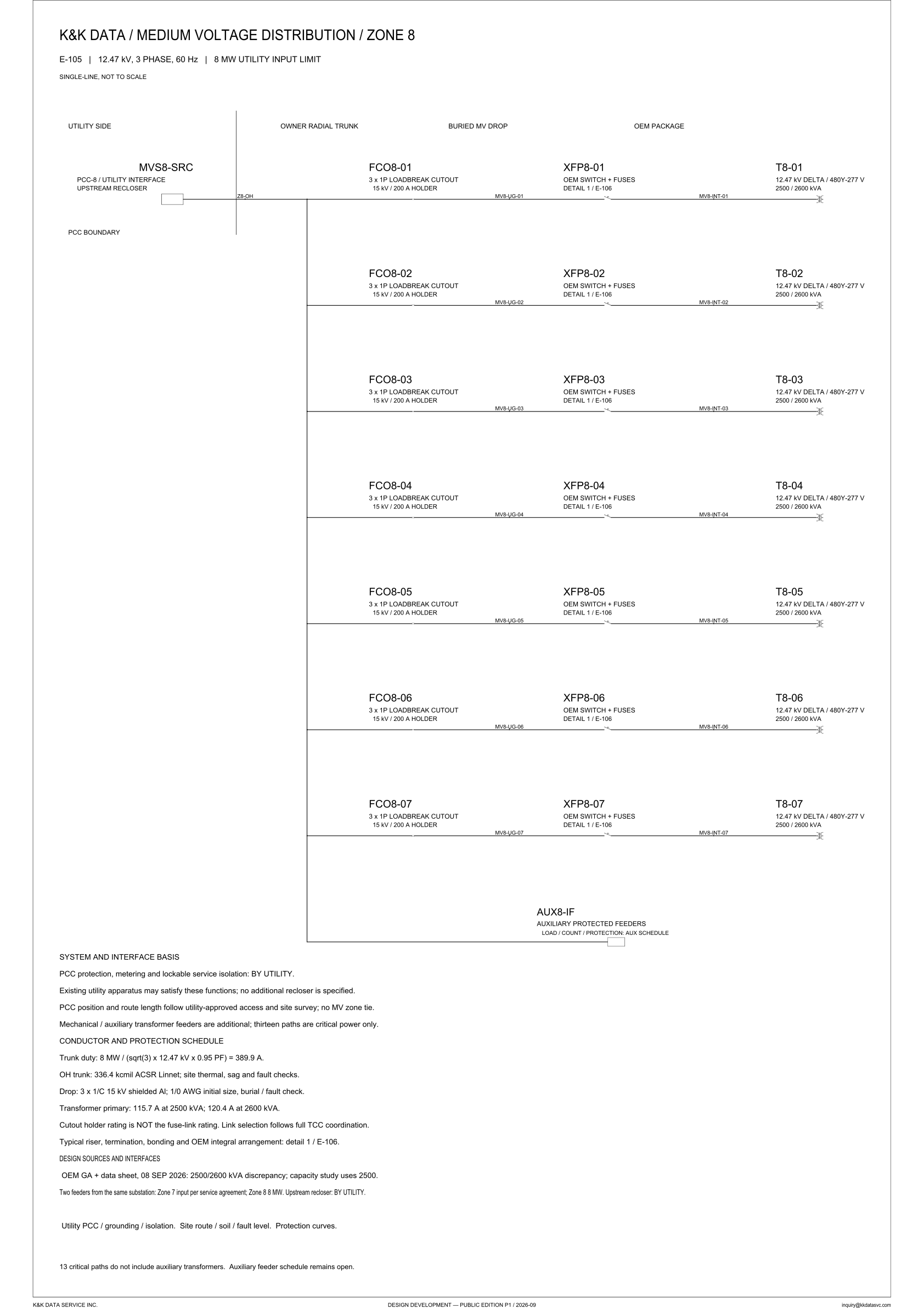
E-105 is the Zone 8 medium-voltage single-line, marked not to scale, for a 12.47 kV, 3-phase, 60 Hz service. The title line states an 8 MW utility input limit. Column headings mark the handoff: utility side, owner radial trunk, buried MV drop, OEM package. MVS8-SRC is the zone source at PCC-8, and the upstream recloser is drawn on the utility side of the vertical line labeled PCC boundary. The owner trunk, tagged Z8-OH, feeds seven paths: loadbreak cutout FCO8-01 through FCO8-07, buried drop MV8-UG-01 through MV8-UG-07, OEM switch and fuses XFP8-01 through XFP8-07 (detail 1 / E-106), internal run MV8-INT-01 through MV8-INT-07, and transformer T8-01 through T8-07. Each transformer block reads 12.47 kV delta / 480Y-277 V and 2500 / 2600 kVA. AUX8-IF leaves the trunk below those seven paths, labeled auxiliary protected feeders rather than another of those paths.
Design intent you can read off the sheet
The PCC is a drawn boundary, and the notes put the duties on the utility side of it. Protection, metering and lockable service isolation are marked BY UTILITY. Existing utility apparatus may satisfy those functions; no additional recloser is specified. Past the boundary the owner has one radial overhead trunk, Z8-OH. The sheet states there is no medium-voltage zone tie. Each of the seven paths has its own cutout, and every transformer tap leaves that same trunk: the cutout is the per-path device, and Z8-OH is the common one. PCC position and route length are not fixed on this sheet; they follow utility-approved access and a site survey. Two feeders come from the same substation: Zone 7 input per the service agreement, and Zone 8 at 8 MW. The upstream recloser remains by the utility. Mechanical and auxiliary transformer feeders are additional. The notes say thirteen paths are critical power only, and the closing line says the 13 critical paths do not include auxiliary transformers. This drawing shows seven Zone 8 transformers, T8-01 through T8-07, and does not draw all thirteen of those paths. Zone 7 is named only as the other feeder. A single radial trunk and no medium-voltage tie are the boundary drawn here; that boundary is taken up in the electrical architecture notes.
Conductor and protection schedule
The conductor schedule prints trunk duty and transformer primary current as separate lines. Trunk duty is 8 MW / (sqrt(3) × 12.47 kV × 0.95 PF) = 389.9 A. The title names an 8 MW utility input limit, and this line uses 8 MW in that quotient. The transformer primary line of the schedule carries 115.7 A at 2500 kVA and 120.4 A at 2600 kVA. Nothing on the sheet adds the path primaries and calls that sum the trunk duty. The overhead conductor is 336.4 kcmil ACSR Linnet. The same line names site thermal, sag and fault checks and does not give their outcome. Each drop is 3 × 1/C 15 kV shielded aluminum, with 1/0 AWG stated as the initial size and a burial and fault check named beside it. Each cutout is 3 × 1P, a 15 kV / 200 A holder. The holder rating is not the fuse-link rating. Link selection follows full TCC coordination, and the sheet prints no fuse-link ampere. Riser, termination, bonding and the OEM integral arrangement are referred to detail 1 / E-106.
Status
Published at Design Development — Public Edition P1 (title block: 2026-09): a reference design for study and evaluation, carrying its open items as sheet notes. An OEM general arrangement and data sheet dated 08 SEP 2026 records a 2500/2600 kVA discrepancy; the capacity study uses 2500, and both numbers remain on every transformer block. The drop conductor is stated as an initial size. No fuse-link ampere is printed. PCC position and route length follow utility-approved access and a site survey. The design-sources block names utility PCC, grounding and isolation; site route, soil and fault level; and protection curves. The one item the sheet itself marks open is the auxiliary feeder schedule. AUX8-IF is a stub labeled auxiliary protected feeders. Its load / count / protection line names an AUX schedule, beside a blank rectangle, and the closing note says the auxiliary feeder schedule remains open.
Sheet guide — the devices on this drawing
MVS8-SRC — PCC-8 utility interface
Zone source on the utility side of the vertical PCC boundary. The tag reads PCC-8 / utility interface, upstream recloser. Notes assign PCC protection, metering and lockable service isolation to the utility. Existing utility apparatus may satisfy those functions; no additional recloser is specified.
Z8-OH — owner radial overhead trunk
The owner trunk, tagged Z8-OH where it crosses the PCC boundary, is the common source for every Zone 8 transformer tap and for the auxiliary stub below. Conductor is 336.4 kcmil ACSR Linnet. The schedule states trunk duty as 8 MW / (sqrt(3) x 12.47 kV x 0.95 PF) = 389.9 A. Site thermal, sag and fault checks are named, with no outcome given on this sheet.
FCO8-01…04 — 15 kV loadbreak cutouts
Four loadbreak cutouts, FCO8-01 through FCO8-04, one tap each off the radial trunk. Each label reads 3 x 1P loadbreak cutout, 15 kV / 200 A holder. The buried drop on the same run is tagged MV8-UG-01 through MV8-UG-04. The holder rating is not the fuse-link rating; link selection follows full TCC coordination, and no link ampere is printed.
FCO8-05…07 — 15 kV loadbreak cutouts
The lower three taps, FCO8-05 through FCO8-07, use the same cutout label as the paths above: 3 x 1P, 15 kV / 200 A holder. Buried drops MV8-UG-05 through MV8-UG-07 leave these cutouts toward the OEM package. The 200 A figure remains the holder rating. The sheet does not print a fuse-link ampere on these taps either.
XFP8-01…04 — OEM fuses and T8-01…04
OEM switch and fuse set on each of the first four paths, XFP8-01 through XFP8-04, each marked detail 1 / E-106. The internal run from the fuses to the transformer is tagged MV8-INT-01 through MV8-INT-04. Transformers T8-01 through T8-04 each read 12.47 kV delta / 480Y-277 V and 2500 / 2600 kVA.
XFP8-05…07 — OEM fuses and T8-05…07
The lower three OEM packages repeat the same chain. XFP8-05 through XFP8-07 are marked detail 1 / E-106, with internal runs MV8-INT-05 through MV8-INT-07. T8-05 through T8-07 carry the same 12.47 kV delta / 480Y-277 V and 2500 / 2600 kVA marking. The schedule lists primary current once, 115.7 A at 2500 kVA and 120.4 A at 2600 kVA, rather than an ampere on each block.
AUX8-IF — auxiliary protected feeders
A stub below the seven transformer paths, with its own label rather than a T8 tag. The text reads auxiliary protected feeders, then load / count / protection: AUX schedule, above a blank rectangle. Notes say mechanical and auxiliary feeders are additional, that 13 critical paths do not include auxiliary transformers, and that this schedule remains open.
System notes — utility PCC, no zone tie
PCC position and route length follow utility-approved access and a site survey, and no medium-voltage zone tie is specified. Two feeders leave the same substation: Zone 7 per the service agreement, Zone 8 at 8 MW, upstream recloser by the utility. Thirteen paths are stated as critical power only; auxiliary transformer feeders are additional to that count.
Conductor schedule — trunk duty and primary amperes
Trunk duty is printed as 8 MW / (sqrt(3) x 12.47 kV x 0.95 PF) = 389.9 A. Overhead conductor 336.4 kcmil ACSR Linnet, with site thermal, sag and fault checks named. Drop 3 x 1/C 15 kV shielded aluminum, 1/0 AWG initial size. Transformer primary 115.7 A at 2500 kVA and 120.4 A at 2600 kVA. The 200 A figure is the cutout holder, not the fuse link.
Design sources — discrepancy and open interfaces
OEM general arrangement and data sheet, 08 SEP 2026: a 2500/2600 kVA discrepancy, with the capacity study using 2500. Interfaces named here and not closed on this sheet are utility PCC, grounding and isolation; site route, soil and fault level; and protection curves. The closing line says the auxiliary feeder schedule remains open.
Get the full drawing set
This sheet is one page of the Electrical Drawing Book — Public Edition P1 (88 pages, 14 MB) — a direct PDF download with a published SHA-256 checksum, no registration. The complete coordinated set is on the downloads page. Background guides: data center one-line diagrams · GB300 NVL72 facility requirements · liquid cooling and CDU design.
Questions about any device or parameter on this sheet: inquiry@kkdatasvc.com or the contact page.