
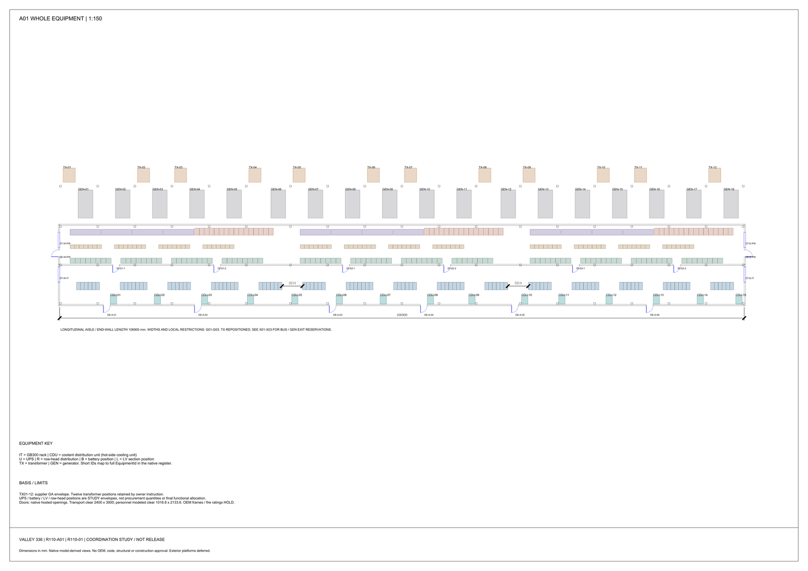
Our liquid-cooling study for the GB300-class reference design now models 18 racks as native pipe: three coolant distribution units (CDUs), six racks on each, and an A and a B secondary train to every rack, 36 rack paths in all [FACT]. The case is PG25 at 44 °C supply, both filters at their end-of-life pressure-drop allowance, and an equal split of 189.9 L/min per rack [STUDY]. The question is whether the secondary side can meet the heat exchanger inlet pressure that the primary side needs. With 3 kPa assigned to the control valve, the worst path in the low-loss case fits by 0.68 kPa. With 5 kPa assigned to the valve, the same path misses by 1.32 kPa. The mid and high cases miss even with zero drop across the valve [STUDY]. The current pipe sizes stay. The parts at the rack end decide the rest.
Where the window comes from
The plate heat exchanger in each CDU has a primary inlet and a secondary inlet. The study keeps the gap between the two inlet pressures at or below 10 kPa, read at stated taps at the same elevation. A fluctuation of 2 kPa either way on each side is counted inside that 10 kPa [STUDY]. The 10 kPa is a pressure-coordination limit. It is not the plate's allowable mechanical differential pressure and not its pressure rating. Both of those are separate checks on the selected unit [HOLD].
The primary side still has two routing options open, one built from elbows and one from a tee. Each puts a different pressure at the primary inlet, and each was checked at 40 °C and 44 °C. The secondary setpoint has to work with either option, so the usable band is the overlap of all four cases. That overlap is 5.01 kPa wide [STUDY]. Both primary options stay inside their own external-loss cap [STUDY].
What the secondary side has to fit
The secondary inlet pressure is a fixed part plus two variable parts. The fixed part was carried from the earlier frozen pressure account: pump suction, both filters, the CDU internals and the rack maker's pressure budget. It was not recalculated here. The variable parts are the loss along the external pipe to the worst rack and back, and the drop across the control valve.
The band therefore gives the two variable parts together a floor and a cap. At zero valve drop the floor is 9.68 kPa. A path below the floor needs extra drop across the control valve: the lowest path in the table, 9.27 kPa, needs at least 0.41 kPa there, so the valve's smallest controllable drop has to cover that [STUDY]. The cap is what limits the external path:
| Control valve drop | Largest allowed external path loss |
|---|---|
| 0 kPa | 14.69 kPa [STUDY] |
| 3 kPa | 11.69 kPa [STUDY] |
| 5 kPa | 9.69 kPa [STUDY] |
The study screens at a 3 kPa valve reserve. The worst rack path in each case, by CDU and train:
| CDU and train | Low-loss case | Mid case | High case |
|---|---|---|---|
| CDU 1, train A | 9.38 kPa | 16.06 kPa | 29.61 kPa |
| CDU 1, train B | 11.01 kPa | 18.02 kPa | 32.05 kPa |
| CDU 2, train A | 9.29 kPa | 15.98 kPa | 29.52 kPa |
| CDU 2, train B | 10.93 kPa | 17.94 kPa | 31.97 kPa |
| CDU 3, train A | 9.27 kPa | 15.95 kPa | 29.50 kPa |
| CDU 3, train B | 10.92 kPa | 17.93 kPa | 31.97 kPa |
All values are [STUDY]. The worst path in the low-loss case is CDU 1, train B, at 11.01 kPa, which leaves 0.68 kPa under the 11.69 kPa cap. On that same path the mid case is 3.33 kPa over the zero-valve cap, and the high case 17.36 kPa over it. Every mid and high path is over that cap; the smallest excess, CDU 3 train A in the mid case, is 1.26 kPa [STUDY]. On every train the worst rack is the last-numbered rack of its group of six. The same train agrees across the three CDUs within about 0.1 kPa. In the low-loss case, train B runs about 1.6 kPa above train A on each CDU.
What the low-loss case assumes
The path loss is counted item by item along the modeled route. It includes the hard pipe, elbows, tees and reducers at their real lengths and flows, an isolation valve, a check valve, two flow measurement points in series, two hoses and the quick connects. The hoses replace the rigid pipe and bends for their own length [STUDY].
The low-loss case measures flow with clamp-on meters on two 300 mm full-bore spool pieces instead of in-line meters. In that case the hard pipe, elbows, tees and reducers come to about 6.96 kPa, and everything else at the rack end comes to about 4.05 kPa, which together make the 11.01 kPa worst path. The cap leaves those other parts about 4.7 kPa [STUDY]. In the screening breakdown, the meters and the hose pair account for most of the spread between the low, mid and high cases [STUDY].
The margin is smaller than one velocity head
Each rack branch carries 189.9 L/min in a 52.5 mm bore. The velocity is 1.46 m/s, and one velocity head of PG25 at 44 °C is 1.093 kPa [STUDY]. Unrounded, the margin is 0.684 kPa, which is 0.63 of a velocity head. One more fitting with a loss coefficient of 0.63 in that bore uses it up.
So the decision sits at the rack end. The loss coefficients that matter belong to parts chosen by the meter, hose, valve and connector suppliers, and the selected-part figures are not yet in hand [HOLD].
Two ways to count the same rack
An independent recalculation used an older set of fitted loss coefficients, counted one meter instead of two, and left the quick connects at the boundary. It agreed with the overlap band and with the 14.69 kPa zero-valve cap. Its mid case for train B came to 17.18 kPa, also outside the band [STUDY].
It picked a different rack as the worst one. Which rack is worst depends on what is counted at the rack end. The study uses the item-by-item count for the decision, and both counts support the same decision.
A second boundary question is still open. It is not yet known whether the hoses and quick connects already sit inside the rack maker's pressure budget [HOLD]. If they are counted there and again here, the loop is penalized twice. If they are in neither place, they are missing. The boundary has to be agreed in writing before a supplier figure can be compared with this table.
What happens next
The current hard-pipe bores, 154.1 mm, 77.9 mm and 52.5 mm, stay as the pricing basis [STUDY]. Release waits on selected-part data at 44 °C PG25 and 189.9 L/min per rack:
- Pressure drop for the hoses and quick connects, the isolation and check valves, both measurement points, the CDU connections and the rack-end assembly. The rack maker states where its budget starts and ends, the lowest flow at the worst rack, and the flow at every rack after balancing.
- A primary-side recheck with the same selected parts against the same external-loss cap, a pump curve on PG25, and the control valve's Kv and usable stroke. The smallest controllable valve drop comes from that data, not from the 3 kPa screen.
- A test that reads both real heat exchanger inlets at the same time, with both filters at their allowance and the racks at design flow. It has to show the 10 kPa limit holding with stable control.
An equal split is a necessary condition only. Each rack reaching its own flow still needs the real rack curves and a balancing plan [HOLD].
Limits and open items
Confirmed: the 36 rack paths are traceable to native pipe segments, fittings and a connection table in the model. [FACT]
Study values: the 5.01 kPa overlap, the floor and the caps, every loss in the tables above, the 0.68 kPa margin, the 1.093 kPa velocity head, and the 6.96 kPa and 4.05 kPa split. Fitting coefficients are a screen, not witnessed fittings. Turns are counted as 90-degree bends. The friction factor of 0.022 is a procurement coefficient, not a Reynolds-number calculation at 44 °C. [STUDY]
Also confirmed: 192 pipe ends in the model are placeholders, 144 for flow meters, 36 for rack hoses and 12 for CDU connections. [FACT]
Open: selected-part pressure data is not in hand for any rack-end part. The pump check uses a water-curve head carried at 2,625 rpm and does not extend to a PG25 pump map. Nothing here is field-measured, and nothing is released for purchase or construction. [HOLD]
Closing observation
Pressure budgets are usually argued on the main pipe, because that is the part on the drawing. In this loop the pipe bores are settled for pricing. What is still open is the pressure drop of each selected rack-end part at 44 °C PG25 and 189.9 L/min, and whether the hoses and quick connects sit inside the rack maker's budget. When the remaining margin is less than one velocity head, those are the questions worth putting to a supplier first.
© 2026 K&K Data Service Inc. All rights reserved. Reproduction or republication is permitted only with clear attribution to K&K Data Service Inc. and a working hyperlink to the canonical URL of this article. Excerpts must preserve the technical context, maturity labels, assumptions, and limitations. No excerpt may imply project approval, field validation, certification, or endorsement that the original article does not state.
Source: K&K Data Service Inc., "With a 3 kPa Valve Reserve, Only the Low-Loss CDU Rack Loop Fits Its Pressure Window, by 0.68 kPa," https://www.kkdatasvc.com/lab/hydraulic-calculation-detail/with-a-3-kpa-valve-reserve-only-the-low-loss-cdu-rack-loop-fits-by-0-68-kpa/.
Questions about this note: email inquiry@kkdatasvc.com and quote KK-DCL-107. Rui Liang replies. If a sheet, a supplier document or a project record gives a different result for the same inputs, send it.