
Data Center Lab · Reference Designs · Electrical
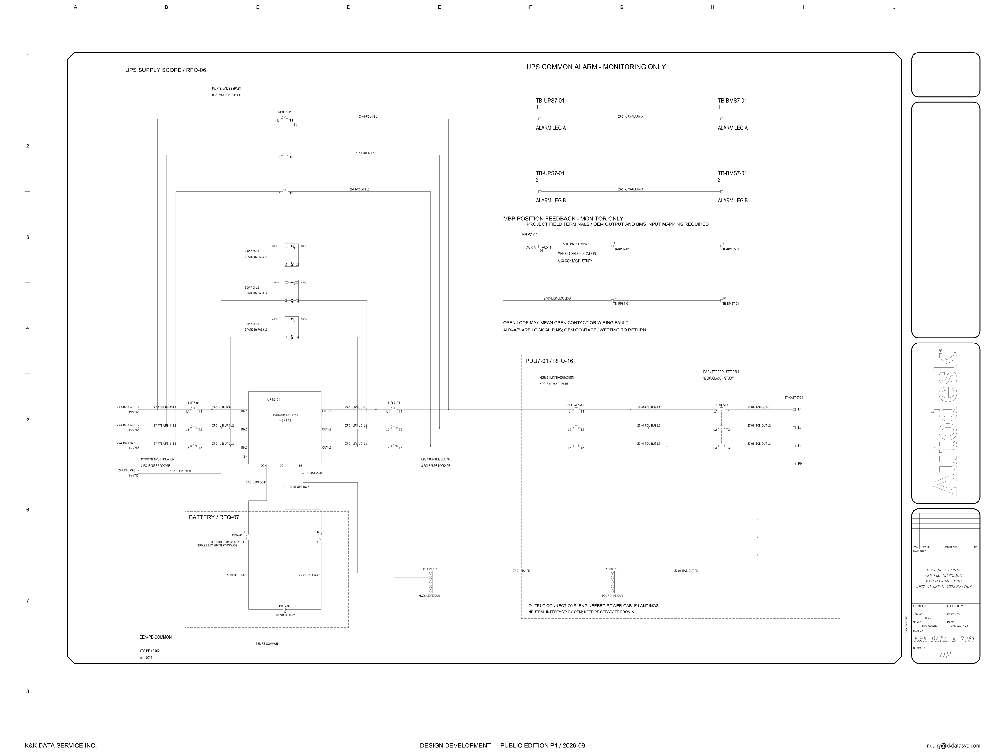
Sheet E-7051: UPS7-01 from the 7021 Supply, through Battery and Bypass, to the PDU
Three supplier scopes share this sheet — UPS package RFQ-06, battery RFQ-07 and PDU RFQ-16 — and the sheet marks bypass-position feedback monitor only and the common alarm monitoring only.
Design Development — Public Edition P1: a reference design for study and evaluation, not a construction issue, not sealed by an Engineer of Record.
Scroll or pinch to zoom, drag to pan, click a highlighted device for its explanation. Vector drawing — it stays sharp at any magnification.
← E-7031 · All electrical sheets
What this sheet shows
E-7051 draws the UPS7-01 interfaces on the supply tagged from 7021. The title block gives drawing number E-7051, date 2026-09-27 / PE-P1, and scale No Scale. Three dashed boxes divide the work. UPS SUPPLY SCOPE / RFQ-06 is the box around UIB7-01, labeled COMMON INPUT ISOLATOR and 3-POLE / UPS PACKAGE; UPS7-01, labeled UPS CONVERSION FUNCTION and 480 V 3 PH; the static bypasses SSW7-01-L1, SSW7-01-L2 and SSW7-01-L3; MBP7-01, labeled MAINTENANCE BYPASS and UPS PACKAGE / 3-POLE; and UOI7-01, labeled UPS OUTPUT ISOLATOR and 3-POLE / UPS PACKAGE. BATTERY / RFQ-07 holds BDI7-01 and BAT7-01. PDU7-01 / RFQ-16 holds PDU7-01-Q0 and ITCB7-01. The phases into the input isolator are Z7-ATS-UPS-01-L1, L2 and L3, each marked from 7021, and the neutral Z7-ATS-UPS-01-N is marked from 7021 as well.
Conversion path, battery, and the rack feeder
UIB7-01 is on the incoming phases. Its load side is Z7-01-UIB-UPS-L1, L2 and L3 into IN-L1, IN-L2 and IN-L3, and the neutral lands on IN-N. OUT-L1, OUT-L2 and OUT-L3 leave UPS7-01 on Z7-01-UPS-UOI-L1, L2 and L3 into UOI7-01. DC+ and DC- leave the same block as Z7-01-UPS-DC-P and Z7-01-UPS-DC-N. In the battery box, BDI7-01 is marked DC PROTECTION - STUDY and 2-POLE STUDY / BATTERY PACKAGE, with terminals B+, U+, U- and B-. Z7-01-BATT-DC-P and Z7-01-BATT-DC-N run to BAT7-01, labeled UPS7-01 BATTERY. No battery voltage is printed. Past the output isolator, inside PDU7-01 / RFQ-16, PDU7-01-Q0 is labeled PDU7-01 MAIN PROTECTION and 3-POLE / UPS7-01 PATH. Z7-01-PDU-BUS-L1, L2 and L3 continue to ITCB7-01, labeled RACK FEEDER - SEE E201 and 3200A CLASS - STUDY. ITCB7-01 feeds IT-OUT-7-01 on Z7-01-ITCB-OUT-L1, L2 and L3, with PE on Z7-01-ITCB-OUT-PE.
Bypasses, and what monitoring is allowed to mean
MBP7-01 and the three static bypasses are drawn in the RFQ-06 box, off the conversion block. SSW7-01-L1, SSW7-01-L2 and SSW7-01-L3 are labeled STATIC BYPASS L1, L2 and L3, and each symbol carries CTRL- and CTRL+. MBP7-01 has F-3 on the symbol, and its load-side tags are Z7-01-PDU-IN-L1, L2 and L3. To the right, position feedback is headed MBP POSITION FEEDBACK - MONITOR ONLY. The line under that reads PROJECT FIELD TERMINALS / OEM OUTPUT AND BMS INPUT MAPPING REQUIRED. The contact is labeled MBP CLOSED INDICATION and AUX CONTACT - STUDY, with AUX-A, AUX-B and C-2. Z7-01-MBP-CLOSED-A lands on terminal 9 of TB-UPS7-01 and terminal 9 of TB-BMS7-01. Z7-01-MBP-CLOSED-B lands on terminal 10 of each block. The note says an open loop may mean an open contact or a wiring fault, and that AUX-A/B are logical pins, with OEM contact and wetting to return. The common alarm is separate, headed UPS COMMON ALARM - MONITORING ONLY: leg A is terminal 1 to terminal 1 on Z7-01-UPS-ALARM-A, and leg B is terminal 2 to terminal 2 on Z7-01-UPS-ALARM-B. That limit is part of the path interface discussed in the electrical architecture notes.
Status
Published at Design Development — Public Edition P1 (title block 2026-09-27 / PE-P1, footer 2026-09): a reference design for study and evaluation. The open items are printed on the sheet. BDI7-01 is marked DC protection study and 2-pole study. ITCB7-01 is marked 3200A class study, and the rack feeder note says see E201. The maintenance-bypass auxiliary is marked aux contact study. The alarm is marked monitoring only, and bypass-position feedback is marked monitor only. OEM output and BMS input mapping is required. AUX-A and AUX-B are logical pins, and OEM contact and wetting are to return. Under the PDU PE bar the sheet prints OUTPUT CONNECTIONS: ENGINEERED POWER-CABLE LANDINGS, and NEUTRAL INTERFACE: BY OEM; KEEP PE SEPARATE FROM N. PE from the conversion block is Z7-01-UPS-PE to the module PE bar PE-UPS7-01. PDU PE is Z7-01-PDU-PE to PE-PDU7-01, labeled PDU7-01 PE BAR, and the feeder PE is Z7-01-ITCB-OUT-PE. Along the bottom, GEN-PE-COMMON is marked from 7021, at the landing labeled ATS PE / E7021.
Sheet guide — the devices on this drawing
UIB7-01 — common input isolator
UIB7-01 is labeled COMMON INPUT ISOLATOR and 3-POLE / UPS PACKAGE. The phases into it are Z7-ATS-UPS-01-L1, L2 and L3, each marked from 7021. The load side is Z7-01-UIB-UPS-L1, L2 and L3 toward the UPS inputs. Neutral Z7-ATS-UPS-01-N, also from 7021, is drawn to IN-N.
UPS7-01 — conversion function, 480 V 3 PH
The block is tagged UPS7-01 and labeled UPS CONVERSION FUNCTION, 480 V 3 PH. The inputs drawn on it are IN-L1, IN-L2, IN-L3 and IN-N. OUT-L1, OUT-L2 and OUT-L3 leave toward the output isolator. DC+ and DC- leave as Z7-01-UPS-DC-P and Z7-01-UPS-DC-N, and PE leaves as Z7-01-UPS-PE.
BDI7-01 / BAT7-01 — battery scope RFQ-07
The dashed box is BATTERY / RFQ-07. BDI7-01 is marked DC PROTECTION - STUDY and 2-POLE STUDY / BATTERY PACKAGE, with terminals B+, U+, U- and B-. Z7-01-BATT-DC-P and Z7-01-BATT-DC-N run to BAT7-01, labeled UPS7-01 BATTERY. No battery voltage is printed on this sheet.
SSW7-01-L1, L2, L3 — static bypass
Three devices are drawn in the inner boxes of the UPS supply scope: SSW7-01-L1, SSW7-01-L2 and SSW7-01-L3, labeled STATIC BYPASS L1, L2 and L3. Each symbol shows CTRL- and CTRL+. The sheet names the function on each phase and prints the control pair beside it.
MBP7-01 — maintenance bypass
MBP7-01 is labeled MAINTENANCE BYPASS and UPS PACKAGE / 3-POLE, with F-3 on the symbol, inside UPS SUPPLY SCOPE / RFQ-06. The load-side tags on the three poles are Z7-01-PDU-IN-L1, L2 and L3. Closed-position feedback for this device is drawn to the right, and that circuit is marked monitor only.
UOI7-01 — UPS output isolator
UOI7-01 is labeled UPS OUTPUT ISOLATOR and 3-POLE / UPS PACKAGE. The conductors from the conversion outputs into it are Z7-01-UPS-UOI-L1, L2 and L3. It sits at the right edge of the UPS supply scope, on the run that continues into the PDU box.
PDU7-01-Q0 / ITCB7-01 — PDU main and rack feeder
Inside PDU7-01 / RFQ-16, PDU7-01-Q0 is labeled PDU7-01 MAIN PROTECTION and 3-POLE / UPS7-01 PATH. Z7-01-PDU-BUS-L1, L2 and L3 continue to ITCB7-01, labeled RACK FEEDER - SEE E201 and 3200A CLASS - STUDY. ITCB7-01 feeds IT-OUT-7-01 on Z7-01-ITCB-OUT-L1, L2 and L3.
TB-UPS7-01 / TB-BMS7-01 — common alarm
The header reads UPS COMMON ALARM - MONITORING ONLY. Alarm leg A is terminal 1 of TB-UPS7-01 to terminal 1 of TB-BMS7-01 on Z7-01-UPS-ALARM-A. Alarm leg B is terminal 2 to terminal 2 on Z7-01-UPS-ALARM-B. The sheet calls this pair monitoring only.
MBP7-01 aux — closed indication, monitor only
The header is MBP POSITION FEEDBACK - MONITOR ONLY, and the next line is PROJECT FIELD TERMINALS / OEM OUTPUT AND BMS INPUT MAPPING REQUIRED. The contact is MBP CLOSED INDICATION, AUX CONTACT - STUDY, with AUX-A, AUX-B and C-2. Z7-01-MBP-CLOSED-A goes to terminal 9, and Z7-01-MBP-CLOSED-B to terminal 10, on TB-UPS7-01 and on TB-BMS7-01. An open loop may mean an open contact or a wiring fault. AUX-A/B are logical pins; OEM contact and wetting are to return.
PE bars — keep PE separate from N
PE-UPS7-01 is the module PE bar, on Z7-01-UPS-PE. PE-PDU7-01 is the PDU7-01 PE bar, on Z7-01-PDU-PE, and Z7-01-ITCB-OUT-PE continues to the output PE. The note under that bar reads OUTPUT CONNECTIONS: ENGINEERED POWER-CABLE LANDINGS, and NEUTRAL INTERFACE: BY OEM; KEEP PE SEPARATE FROM N.
Get the full drawing set
This sheet is one page of the Electrical Drawing Book — Public Edition P1 (88 pages, 14 MB) — a direct PDF download with a published SHA-256 checksum, no registration. The complete coordinated set is on the downloads page. Background guides: data center one-line diagrams · GB300 NVL72 facility requirements · liquid cooling and CDU design.
Questions about any device or parameter on this sheet: inquiry@kkdatasvc.com or the contact page.