
Data Center Lab · Reference Designs · Electrical
Sheet E-7031: One SEG-A Close-Permit Pair to ATS7-01, and the Start Request In
One pair from generator plant SEG-A carries both the capacity declaration and the staged close permit to ATS7-01, and loss of that permit blocks a new close only.
Design Development — Public Edition P1: a reference design for study and evaluation, not a construction issue, not sealed by an Engineer of Record.
Scroll or pinch to zoom, drag to pan, click a highlighted device for its explanation. Vector drawing — it stays sharp at any magnification.
← E-7021 · All electrical sheets · E-7051 →
What this sheet shows
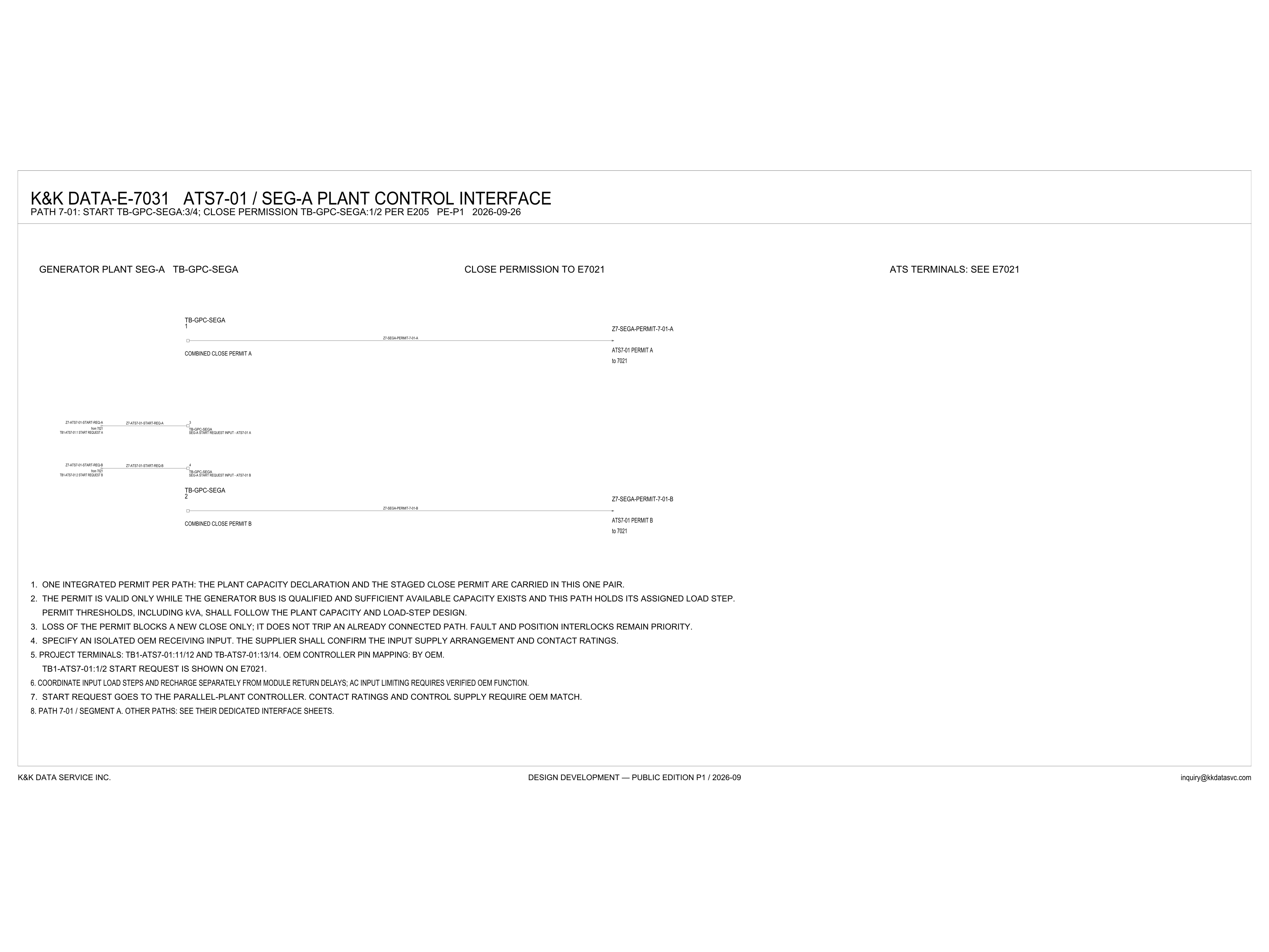
E-7031 is the control interface between generator plant SEG-A and ATS7-01 for path 7-01. The title reads ATS7-01 / SEG-A plant control interface, revision PE-P1, dated 2026-09-26. The path line under it assigns the plant terminals: start on TB-GPC-SEGA:3/4, and close permission on TB-GPC-SEGA:1/2, per E205. Three headers name the parties on the sheet. The left header is generator plant SEG-A, terminal block TB-GPC-SEGA. The center header is close permission to E7021. The right header reads ATS terminals: see E7021, and no ATS terminal strip is drawn under it. Combined close permit A is terminal 1, conductor Z7-SEGA-PERMIT-7-01-A, labeled ATS7-01 permit A, to 7021. Combined close permit B is terminal 2, conductor Z7-SEGA-PERMIT-7-01-B, labeled ATS7-01 permit B, to 7021. The start request is marked from 7021. TB1-ATS7-01:1 start request A, conductor Z7-ATS7-01-START-REQ-A, lands on terminal 3, labeled SEG-A start request input - ATS7-01 A. TB1-ATS7-01:2 start request B, conductor Z7-ATS7-01-START-REQ-B, lands on terminal 4, labeled SEG-A start request input - ATS7-01 B.
What the one pair carries
Note 1 calls this one integrated permit per path: the plant capacity declaration and the staged close permit are carried in this one pair, conductors Z7-SEGA-PERMIT-7-01-A and Z7-SEGA-PERMIT-7-01-B. Note 2 states the permit is valid only while the generator bus is qualified and sufficient available capacity exists and this path holds its assigned load step. Permit thresholds, including kVA, shall follow the plant capacity and load-step design. No kVA number is printed on this sheet. Note 3 states the effect of loss: loss of the permit blocks a new close only; it does not trip an already connected path. Fault and position interlocks remain priority. That limit is part of the path architecture discussed in the electrical architecture notes.
Start request, and the match still open
Note 7 says the start request goes to the parallel-plant controller. Contact ratings and control supply require OEM match. The drawing shows that request as the pair from 7021 into TB-GPC-SEGA: TB1-ATS7-01:1 start request A on Z7-ATS7-01-START-REQ-A at terminal 3, and TB1-ATS7-01:2 start request B on Z7-ATS7-01-START-REQ-B at terminal 4. Note 5 says the TB1-ATS7-01:1/2 start request is shown on E7021. The same note names project terminals TB1-ATS7-01:11/12 and TB-ATS7-01:13/14, and it states OEM controller pin mapping: by OEM. Note 4 says to specify an isolated OEM receiving input. The supplier shall confirm the input supply arrangement and contact ratings. Note 6 says to coordinate input load steps and recharge separately from module return delays, and that AC input limiting requires verified OEM function. Note 8 sets the sheet's scope: path 7-01 / segment A. Other paths: see their dedicated interface sheets.
Status
Published at Design Development — Public Edition P1 (title block 2026-09-26, revision PE-P1; footer 2026-09): a reference design for study and evaluation. What the sheet states is the terminal assignment on TB-GPC-SEGA, the one pair that carries the capacity declaration and the staged close permit, the conditions in note 2, and the rule that loss of the permit blocks a new close only and does not trip an already connected path. What it leaves for confirmation is written as supplier and OEM work: an isolated OEM receiving input, with the input supply arrangement and contact ratings for the supplier to confirm; OEM controller pin mapping by the OEM; contact ratings and control supply that require OEM match; and AC input limiting, which the note says requires verified OEM function. Permit thresholds, including kVA, shall follow the plant capacity and load-step design.
Sheet guide — the devices on this drawing
E-7031 — path 7-01 terminal assignment
The sheet title is ATS7-01 / SEG-A plant control interface. The path line reads: start TB-GPC-SEGA:3/4; close permission TB-GPC-SEGA:1/2 per E205. The revision is PE-P1, dated 2026-09-26. That line is the assignment for the four TB-GPC-SEGA terminals drawn below.
ATS terminals — see E7021
The right-hand header reads ATS terminals: see E7021. The ATS terminal strip is not drawn on this sheet. Note 5 names project terminals TB1-ATS7-01:11/12 and TB-ATS7-01:13/14, and it states OEM controller pin mapping: by OEM. The same note says the TB1-ATS7-01:1/2 start request is shown on E7021.
TB-GPC-SEGA:1 — combined close permit A
Terminal 1 of TB-GPC-SEGA is labeled combined close permit A. The conductor is Z7-SEGA-PERMIT-7-01-A, and the far end is labeled ATS7-01 permit A, to 7021. The path line names terminals 1 and 2 as the close permission. Note 1 says this one pair carries the plant capacity declaration and the staged close permit.
TB-GPC-SEGA:3/4 — SEG-A start request from 7021
Terminal 3 is labeled SEG-A start request input - ATS7-01 A. It takes conductor Z7-ATS7-01-START-REQ-A from TB1-ATS7-01:1, marked from 7021. Terminal 4 is labeled SEG-A start request input - ATS7-01 B, on Z7-ATS7-01-START-REQ-B from TB1-ATS7-01:2, also from 7021. Note 7 says the start request goes to the parallel-plant controller.
TB-GPC-SEGA:2 — combined close permit B
Terminal 2 of TB-GPC-SEGA is labeled combined close permit B. The conductor is Z7-SEGA-PERMIT-7-01-B, and the far end is labeled ATS7-01 permit B, to 7021. With terminal 1, this is the one pair in note 1. Note 3 applies to that permit: loss blocks a new close only, and it does not trip an already connected path.
Notes 1–3 — permit pair, validity, and loss
Note 1 carries the plant capacity declaration and the staged close permit in this one pair. Note 2 holds the permit valid only while the generator bus is qualified, sufficient available capacity exists, and this path holds its assigned load step. Thresholds, including kVA, follow the plant capacity and load-step design. Note 3: loss of the permit blocks a new close only and does not trip an already connected path. Fault and position interlocks remain priority.
Notes 4–8 — OEM match and segment A scope
Note 4 says to specify an isolated OEM receiving input, and that the supplier shall confirm the input supply arrangement and contact ratings. Note 5 leaves the controller pin mapping by the OEM. Note 6 says to coordinate input load steps and recharge separately from module return delays, and that AC input limiting requires verified OEM function. Note 7 says contact ratings and control supply require OEM match. Note 8 limits this sheet to path 7-01 / segment A. Other paths: see their dedicated interface sheets.
Get the full drawing set
This sheet is one page of the Electrical Drawing Book — Public Edition P1 (88 pages, 14 MB) — a direct PDF download with a published SHA-256 checksum, no registration. The complete coordinated set is on the downloads page. Background guides: data center one-line diagrams · GB300 NVL72 facility requirements · liquid cooling and CDU design.
Questions about any device or parameter on this sheet: inquiry@kkdatasvc.com or the contact page.