
Data Center Lab · Reference Designs · Electrical
Sheet E-7021: ATS7-01 as One UL 1008 Assembly, with Permission and Project Terminals
The transfer rules, the close permit, marked study, and the cabinet outline are all on this sheet, and several of them are still marked as supplier or OEM returns.
Design Development — Public Edition P1: a reference design for study and evaluation, not a construction issue, not sealed by an Engineer of Record.
Scroll or pinch to zoom, drag to pan, click a highlighted device for its explanation. Vector drawing — it stays sharp at any magnification.
← E-7061 · All electrical sheets · E-7031 →
What this sheet shows
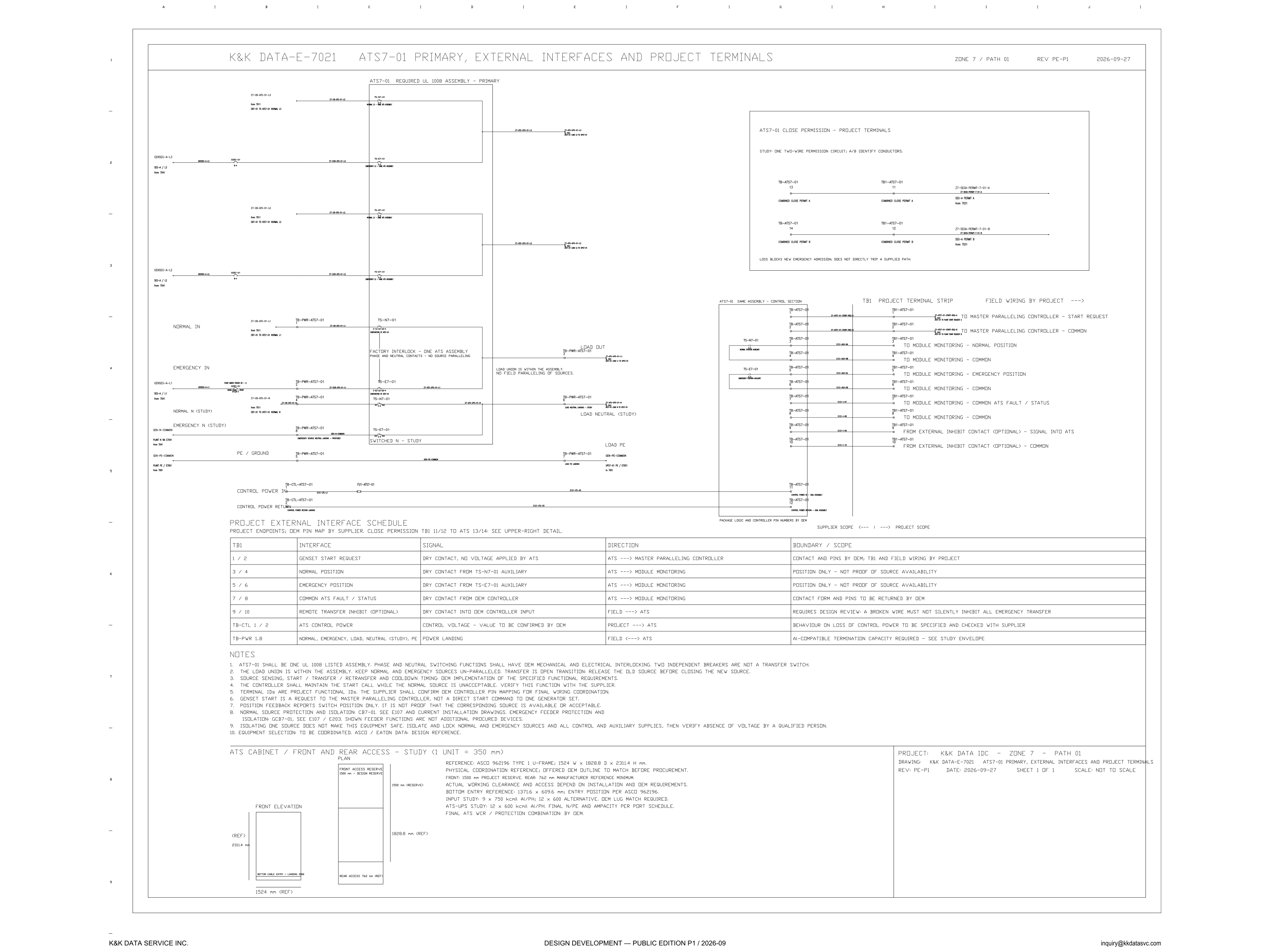
E-7021 is the primary sheet for ATS7-01 on Zone 7, path 01. The title block reads ATS7-01 primary, external interfaces and project terminals, revision PE-P1, dated 2026-09-27, sheet 1 of 1, and not to scale. The upper left is the power assembly, titled required UL 1008 assembly. Normal phases arrive from 7011, labeled CB7-01 to ATS7-01 normal, on Z7-CB-ATS-01-L1, L2 and L3. Emergency in arrives from 7041. Normal N and emergency N are drawn under the phases and marked study, and the switched neutral is labeled switched N — study. Load out, load neutral (study) and load PE leave through TB-PWR-ATS7-01. The line inside the assembly states the factory interlock: one ATS assembly, phase and neutral contacts, no source paralleling. Beside the load it says the load union is within the assembly and there is no field paralleling of sources. Control power is a separate pair under the PE, landed on TB-CTL-ATS7-01 with a return. The upper right is the close-permission detail. Under that, the control section of the same assembly faces TB1, the project terminal strip, with field wiring by the project. The lower half holds the external-interface schedule, the notes, and a front-and-rear access study of the cabinet.
Transfer rules the notes actually state
The notes carry the architecture, and they also mark what is not yet selected. ATS7-01 shall be one UL 1008 listed assembly. Phase and neutral switching functions shall have OEM mechanical and electrical interlocking. Two independent breakers are not a transfer switch. The load union stays inside the assembly, normal and emergency sources are kept un-paralleled, and transfer is open transition: release the old source before closing the new source. Source sensing, start, transfer, retransfer and cooldown timing are named as the OEM implementation of the specified functional requirements. The controller shall maintain the start call while the normal source is unacceptable, and the note says to verify that function with the supplier. Genset start is a request to the master paralleling controller, not a direct start command to one generator set. Position feedback reports switch position only. It is not proof that the corresponding source is available or acceptable. Normal-source protection and isolation are named as CB7-01, with a pointer to E107 / E203. The shown feeder functions are not additional procured devices, and the line runs on to emergency feeder protection. Isolating one source does not make this equipment safe: both sources, and all control and auxiliary supplies, are to be isolated and locked, and absence of voltage verified by a qualified person. Equipment selection is to be coordinated to the ASCO / Eaton data design reference. That open-transition boundary is discussed in the electrical architecture notes.
Project terminals and what each contact means
Close permission is marked study: one two-wire circuit, with A and B identity conductors. Package terminals TB-ATS7-01 13 and 14 face project terminals TB1-ATS7-01 11 and 12. The conductors are Z7-SEGA-PERMIT-7-01-A and Z7-SEGA-PERMIT-7-01-B, combined close permit A and B, from 7031. The line under the detail says loss blocks new emergency admission and does not directly trip a supplied path. On TB1, terminals 1 and 2 are the genset start request and its common: a dry contact, no voltage applied by the ATS, directed to the master paralleling controller. Contact and pins are by the OEM; TB1 and the field wiring are by the project. Terminals 3 and 4 are normal position from the TS-N7-01 auxiliary, and terminals 5 and 6 are emergency position from the TS-E7-01 auxiliary. Both rows are marked position only, not proof of source availability, which is the same limit as the position note. Terminals 7 and 8 are the common ATS fault / status contact from the OEM controller, and the contact form and pins are to be returned by the OEM. Terminals 9 and 10 are an optional remote transfer inhibit, a dry contact into the OEM controller input, from the field into the ATS. That row requires a design review, and it states the criterion in words: a broken wire must not silently inhibit all emergency transfer. Control power is TB-CTL 1/2, project to ATS. The control voltage value is to be confirmed by the OEM, and behaviour on loss of control power is to be specified and checked with the supplier. The power landings are TB-PWR 1 through 8, covering normal, emergency, load, neutral (study) and PE, with termination capacity required and a pointer to the study envelope. Terminal IDs here are project functional IDs. The supplier confirms OEM controller pin mapping for final wiring coordination, and package logic and controller pin numbers are by the OEM.
Cabinet study, and the match still open
The access view is titled a study, with the unit note 1 unit = 350 mm, while the sheet title block says not to scale. The reference names ASCO 962196, type 1 U-frame, 1524 mm wide by 1828.8 mm deep by 2314 mm high, and it calls that outline a physical coordination reference: the offered OEM outline is to be matched before procurement. Front access is a 1500 mm project reserve. Rear access is 762 mm, a manufacturer reference minimum. Actual working clearance and access depend on installation and OEM requirements. Bottom entry is a reference of 1371.6 mm by 609.6 mm, entry position per ASCO 962196. The input study is 9 × 750 kcmil Al/PH, with 12 × 600 as the alternative, and OEM lug match is required. The ATS-UPS study is 12 × 600 kcmil Al/PH, with final N/PE and ampacity per the port schedule. The final ATS WCR and protection combination is by the OEM. Read with the notes, the sheet states requirements and leaves these interface items open: the close-permission detail is marked study, the inhibit row requires design review, the start call is to be verified with the supplier, and the OEM pin map is for the supplier to confirm. The hardware match stays open on outline, lugs, clearances, control-power behaviour, and the neutral, which is marked study on the normal, emergency, switched and load neutrals. An SPD-01 callout at the load PE marks N as TBD. Published at Design Development — Public Edition P1 (title block 2026-09-27; footer 2026-09): a reference design for study and evaluation.
Sheet guide — the devices on this drawing
ATS7-01 — required UL 1008 assembly
The primary view is titled required UL 1008 assembly. Normal phases land from 7011, labeled CB7-01 to ATS7-01 normal, on Z7-CB-ATS-01-L1, L2 and L3. Emergency in arrives from 7041. The factory interlock says one ATS assembly, phase and neutral contacts, no source paralleling, and beside the load the sheet says the load union is within the assembly, with no field paralleling of sources. Load out leaves on TB-PWR-ATS7-01.
Switched N — neutral and load PE study
Normal N and emergency N are both marked study, and the switched neutral is labeled switched N — study. Load neutral carries the same study mark. Load PE is a power landing on TB-PWR-ATS7-01, with GEN-PE-COMMON on that landing and an SPD-01 callout whose N is marked TBD. The schedule repeats that landing as neutral (study). The neutral path on this sheet is marked study.
TB1-ATS7-01 11/12 — combined close permit
The detail is marked study: one two-wire permission circuit, with A and B identity conductors. Package terminals TB-ATS7-01 13 and 14 face project terminals TB1-ATS7-01 11 and 12. The pair is Z7-SEGA-PERMIT-7-01-A and Z7-SEGA-PERMIT-7-01-B, combined close permit, from 7031. Loss blocks new emergency admission and does not directly trip a supplied path.
TB1-ATS7-01 — project terminal strip
The strip is the control section of the same ATS7-01 assembly. Field wiring is by the project; package logic and controller pin numbers are by the OEM. Terminals 1 and 2 are the start request to the master paralleling controller and its common. Terminals 3 through 8 are the monitoring contacts. Terminals 9 and 10 are the optional external inhibit into the ATS. Supplier scope is on the package side of the terminals, project scope on the field side.
Interface schedule — what each contact is
The header calls these project endpoints, with the OEM pin map by the supplier, and it points to the upper-right detail for close permission on TB1 11/12 to ATS 13/14. Start is a dry contact with no voltage applied by the ATS. Normal and emergency position come from the TS-N7-01 and TS-E7-01 auxiliaries. Fault status is a dry contact from the OEM controller. The inhibit row is optional, a dry contact into the controller.
Boundary column — returns still open
Start contacts and pins are by the OEM; TB1 and field wiring are by the project. The position rows are marked position only, not proof of source availability. Fault-contact form and pins are to be returned by the OEM. The inhibit row requires a design review: a broken wire must not silently inhibit all emergency transfer. Control voltage is to be confirmed by the OEM, and behaviour on loss of control power is to be specified and checked with the supplier. Power termination capacity is required, and that row points to the study envelope.
Transfer notes — one assembly, open items
The notes require one UL 1008 listed assembly with OEM mechanical and electrical interlocking, and they say two independent breakers are not a transfer switch. Transfer is open transition: release the old source before closing the new. The controller shall maintain the start call while the normal source is unacceptable, and that function is to be verified with the supplier. Genset start is a request to the master paralleling controller, not a direct start command to one generator set. Normal-source protection and isolation are named as CB7-01; see E107 / E203. The shown feeder functions are not additional procured devices, and the note then names emergency feeder protection.
Front elevation — 1500 mm reserve, 762 mm rear
The plan and front elevation are a study of front and rear access. The front is marked as a 1500 mm project reserve. The rear is 762 mm, called a manufacturer reference minimum on the reference line beside the view. The elevation carries the reference outline, 1524 mm wide and 2314 mm high, with 1828.8 mm on the depth. Actual working clearance still depends on installation and OEM requirements.
ASCO 962196 — outline, entry and lug study
The reference names ASCO 962196, type 1 U-frame, 1524 W x 1828.8 D x 2314 H mm, and says the offered OEM outline is to be matched before procurement. Bottom entry reference is 1371.6 x 609.6 mm, with the entry position per that ASCO number. The input study is 9 x 750 kcmil Al/PH, with 12 x 600 as the alternative, and OEM lug match required. The ATS-UPS study is 12 x 600 kcmil Al/PH. Final N/PE, ampacity and the ATS WCR / protection combination are by the OEM.
Get the full drawing set
This sheet is one page of the Electrical Drawing Book — Public Edition P1 (88 pages, 14 MB) — a direct PDF download with a published SHA-256 checksum, no registration. The complete coordinated set is on the downloads page. Background guides: data center one-line diagrams · GB300 NVL72 facility requirements · liquid cooling and CDU design.
Questions about any device or parameter on this sheet: inquiry@kkdatasvc.com or the contact page.