
Data Center Lab · Reference Designs · Electrical
Sheet E-7061: Continuous Plant Neutral and the Single Designated N-PE Bond
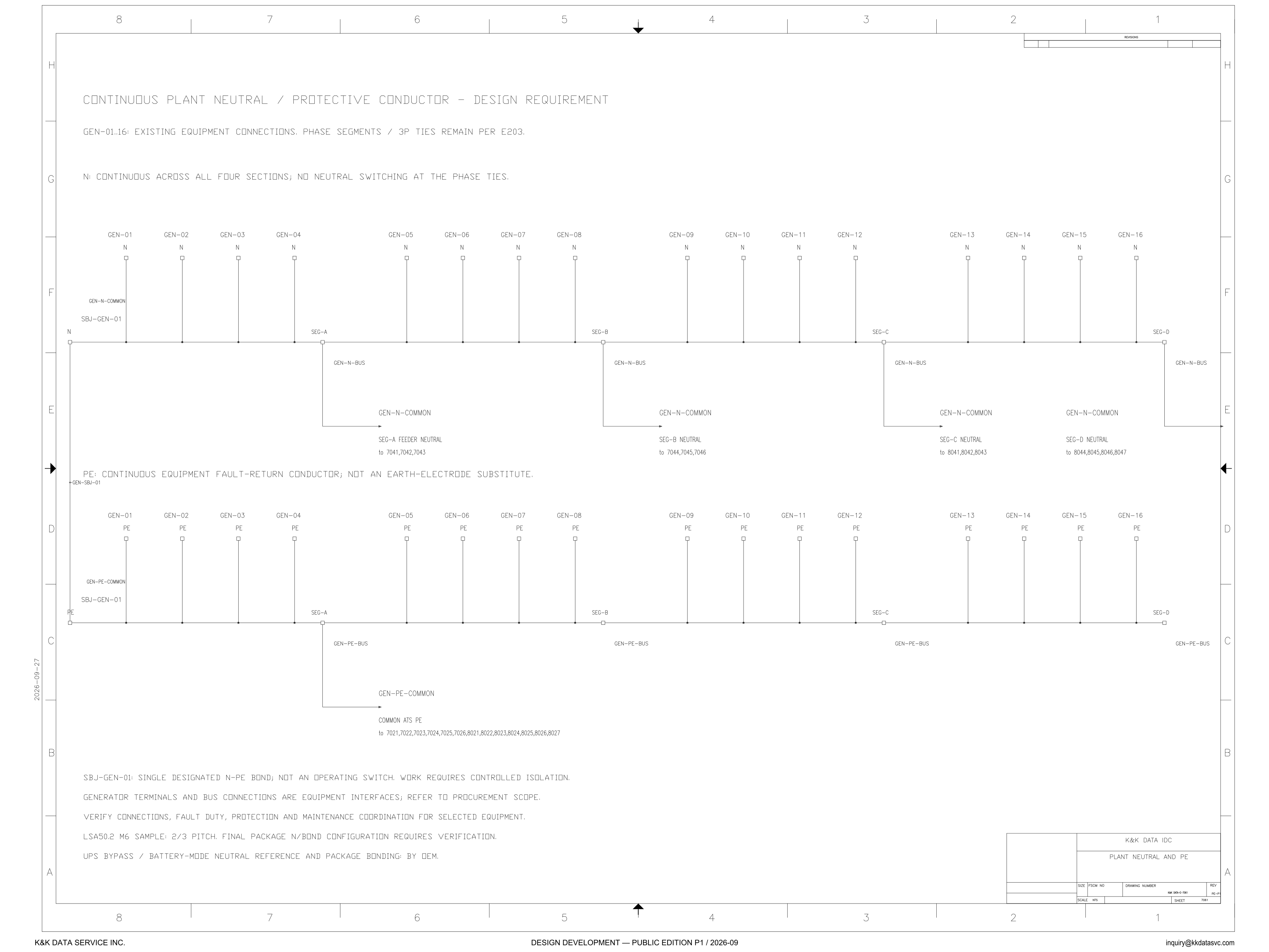
N is continuous across all four sections, with no neutral switching at the phase ties, and SBJ-GEN-01 is named as the single designated N-PE bond.
Design Development — Public Edition P1: a reference design for study and evaluation, not a construction issue, not sealed by an Engineer of Record.
Scroll or pinch to zoom, drag to pan, click a highlighted device for its explanation. Vector drawing — it stays sharp at any magnification.
← E-7011 · All electrical sheets · E-7021 →
What this sheet shows
E-7061 is the plant neutral and protective-conductor sheet. The heading reads continuous plant neutral / protective conductor, and it calls that pair a design requirement. The line under the heading reads GEN-01..16: existing equipment connections, and phase segments / 3P ties remain per E203. Each machine in GEN-01..16 has an N terminal on the upper conductor and a PE terminal on the lower conductor. The note on the neutral says N is continuous across all four sections, with no neutral switching at the phase ties. The same section letters, SEG-A, SEG-B, SEG-C and SEG-D, are marked along both conductors. The left-hand neutral node is labeled N, GEN-N-COMMON and SBJ-GEN-01. The left-hand PE node is labeled PE, GEN-PE-COMMON and SBJ-GEN-01. An arrow at the left of the PE sentence is tagged +GEN-SBJ-01.
Where each conductor leaves the bus
Each neutral section takes off through a drop marked GEN-N-BUS and a leader marked GEN-N-COMMON, the same GEN-N-COMMON text that is also printed at the left-hand node. Under SEG-A the leader reads SEG-A FEEDER NEUTRAL to 7041,7042,7043. Under SEG-B it reads SEG-B NEUTRAL to 7044,7045,7046. Under SEG-C it reads SEG-C NEUTRAL to 8041,8042,8043. Under SEG-D it reads SEG-D NEUTRAL to 8044,8045,8046,8047, and that leader runs to an arrow at the right border. Only the SEG-A line uses the words feeder neutral, and only the SEG-D line names four destinations. The PE sentence calls the lower conductor a continuous equipment fault-return conductor, and it says that conductor is not an earth-electrode substitute. The PE leader that carries a destination leaves the node at SEG-A, marked GEN-PE-BUS and then GEN-PE-COMMON. The text under it reads COMMON ATS PE to 7021,7022,7023,7024,7025,7026,8021,8022,8023,8024,8025,8026,8027. Neutral destinations are printed section by section. The ATS protective earth is printed as one list. That split is what this sheet draws; how a boundary of this kind is read is discussed in the electrical architecture notes.
The bond note, the sample, and the OEM line
The notes under the diagram define SBJ-GEN-01, then print the procurement, verification, and OEM lines. The bond note reads: single designated N-PE bond; not an operating switch. Work requires controlled isolation. Generator terminals and bus connections are equipment interfaces; refer to procurement scope. The next line says to verify connections, fault duty, protection and maintenance coordination for the selected equipment. The machine line is printed as a sample: LSA50.2 M6, 2/3 pitch, and the same line says the final package N/bond configuration requires verification. The last line assigns the UPS bypass / battery-mode neutral reference and the package bonding to the OEM.
Status
The issue is Design Development — Public Edition P1, a reference design for study and evaluation. The footer carries 2026-09, and the date on the left border is 2026-09-27. The title block reads PLANT NEUTRAL AND PE, the sheet cell reads 7061, and the scale reads NTS. The requirement printed on the sheet is the continuous neutral across all four sections, no neutral switching at the phase ties, and the single designated N-PE bond. The notes qualify the rest in their own words: LSA50.2 M6 is a sample at 2/3 pitch, the final package N/bond configuration requires verification, the UPS bypass and battery-mode neutral reference and the package bonding are by OEM, and the generator terminals and bus connections are referred to procurement scope.
Sheet guide — the devices on this drawing
GEN-01..16 — existing equipment connections
The heading calls the continuous plant neutral and protective conductor a design requirement. The line under it reads GEN-01..16: existing equipment connections, and phase segments / 3P ties remain per E203. The neutral note says N is continuous across all four sections, with no neutral switching at the phase ties.
SBJ-GEN-01 — single designated N-PE bond
The left-hand neutral node is labeled N, GEN-N-COMMON, SBJ-GEN-01, and the left-hand PE node is labeled PE, GEN-PE-COMMON, SBJ-GEN-01. The note calls SBJ-GEN-01 the single designated N-PE bond, not an operating switch, and says work requires controlled isolation. The arrow on the PE sentence is tagged +GEN-SBJ-01.
SEG-A — feeder neutral to 7041,7042,7043
The SEG-A machines land their N terminals on the continuous neutral. At the section node the drop is marked GEN-N-BUS and the leader is marked GEN-N-COMMON. The text under that leader reads SEG-A FEEDER NEUTRAL to 7041,7042,7043, the only leader that uses the words feeder neutral.
SEG-B — neutral to 7044,7045,7046
SEG-B is the next four machines on the same continuous neutral. The drop is marked GEN-N-BUS and the leader is marked GEN-N-COMMON, the same two marks used at the other sections. The line under the leader reads SEG-B NEUTRAL to 7044,7045,7046.
SEG-C — neutral to 8041,8042,8043
SEG-C keeps the same neutral bus: four N terminals, a GEN-N-BUS drop, and a GEN-N-COMMON leader. The destination line reads SEG-C NEUTRAL to 8041,8042,8043. The words feeder neutral are printed under SEG-A; this leader reads SEG-C NEUTRAL.
SEG-D — neutral to 8044,8045,8046,8047
SEG-D is the last group on the neutral. Its leader reads SEG-D NEUTRAL to 8044,8045,8046,8047, which is the destination line that names four numbers. The leader runs on to an arrow at the right border.
PE — continuous equipment fault-return conductor
The sentence on this conductor reads: continuous equipment fault-return conductor; not an earth-electrode substitute. Each machine in GEN-01..16 has a PE terminal on it, and the left node repeats SBJ-GEN-01 with the label GEN-PE-COMMON. SEG-A, SEG-B, SEG-C and SEG-D are marked on this bus as well.
GEN-PE-COMMON — common ATS PE
From the node at SEG-A the PE drops on a lead marked GEN-PE-BUS and turns onto a leader marked GEN-PE-COMMON. The text under that leader is COMMON ATS PE to 7021,7022,7023,7024,7025,7026,8021,8022,8023,8024,8025,8026,8027. The neutral leaders above are split by section; this ATS protective earth is one printed list.
SEG-C / SEG-D — PE bus and GEN-PE-BUS
The PE terminals in SEG-C and SEG-D land on the same continuous bus, and GEN-PE-BUS is printed at those section nodes. The destination words read for this conductor are the COMMON ATS PE list on the SEG-A leader. The PE bus ends at the SEG-D node, with GEN-PE-BUS under that node.
Notes — bond, sample pitch, and OEM bonding
SBJ-GEN-01 is the single designated N-PE bond, not an operating switch, and work requires controlled isolation. Generator terminals and bus connections are equipment interfaces, referred to procurement scope, and the sheet says to verify connections, fault duty, protection and maintenance coordination for the selected equipment. LSA50.2 M6 is a sample at 2/3 pitch; the final package N/bond configuration requires verification; the UPS bypass / battery-mode neutral reference and package bonding are by OEM.
Get the full drawing set
This sheet is one page of the Electrical Drawing Book — Public Edition P1 (88 pages, 14 MB) — a direct PDF download with a published SHA-256 checksum, no registration. The complete coordinated set is on the downloads page. Background guides: data center one-line diagrams · GB300 NVL72 facility requirements · liquid cooling and CDU design.
Questions about any device or parameter on this sheet: inquiry@kkdatasvc.com or the contact page.