
Data Center Lab · Reference Designs · Electrical
Sheet E-7011: Path 7-01 Landings from the 12.47 kV Boundary to the ATS Normal Terminals
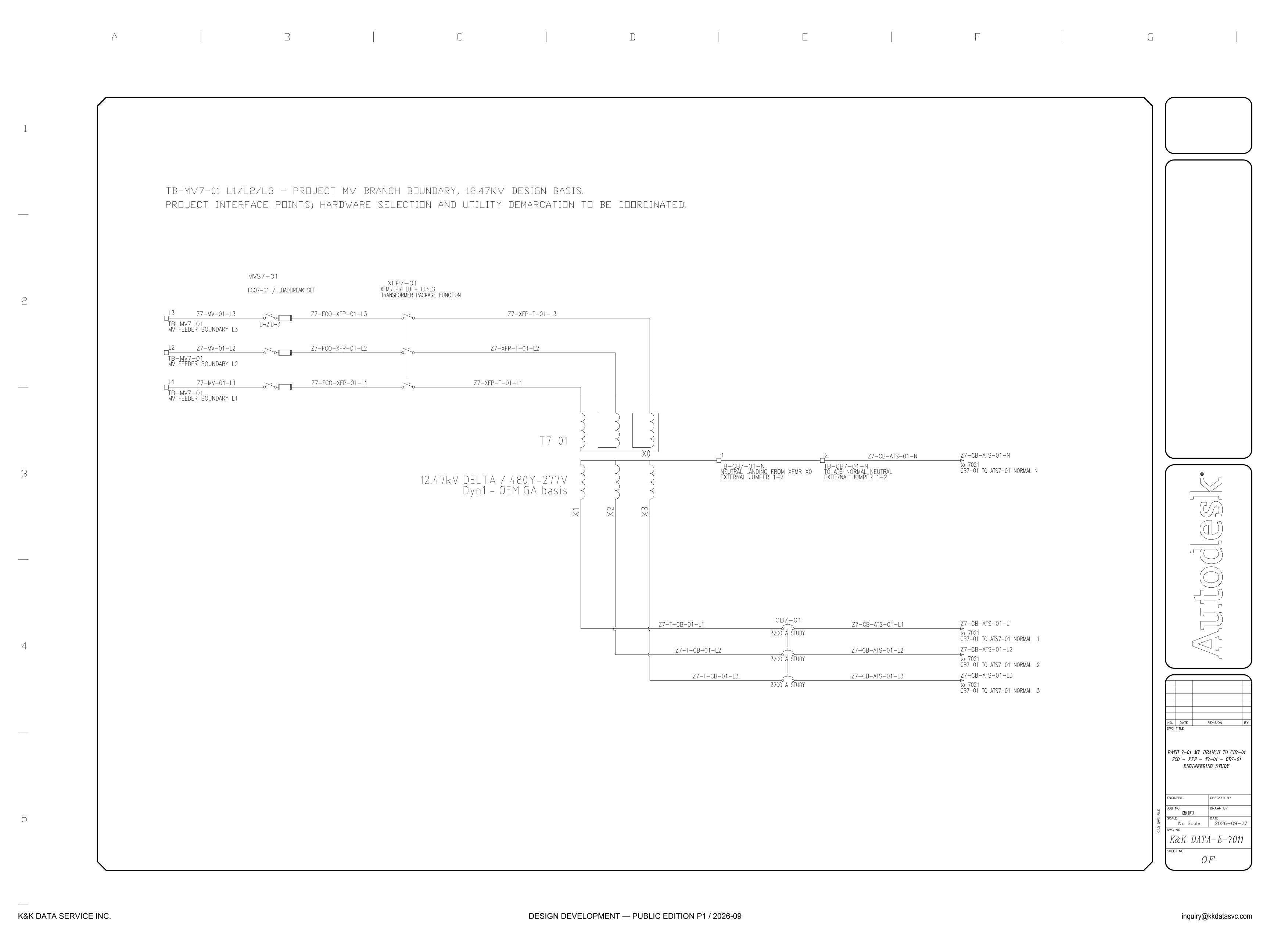
Path 7-01 is drawn landing by landing from the 12.47 kV branch boundary to the ATS normal terminals, with hardware selection and utility demarcation to be coordinated and each breaker pole marked 3200 A STUDY.
Design Development — Public Edition P1: a reference design for study and evaluation, not a construction issue, not sealed by an Engineer of Record.
Scroll or pinch to zoom, drag to pan, click a highlighted device for its explanation. Vector drawing — it stays sharp at any magnification.
← E-315 · All electrical sheets · E-7061 →
What this sheet shows
E-7011 is the engineering study of path 7-01 from the project MV branch boundary to CB7-01, with each phase drawn and named rather than collapsed to one line. The note at the head of the sheet calls TB-MV7-01 L1/L2/L3 the project MV branch boundary, on a 12.47 kV design basis. Each phase lands on its own TB-MV7-01 terminal, marked MV feeder boundary, and leaves that terminal as Z7-MV-01-L1, Z7-MV-01-L2 or Z7-MV-01-L3 into MVS7-01 and FCO7-01 / LOADBREAK SET. Beyond FCO7-01 the same three phases are Z7-FCO-XFP-01-L1, L2 and L3 into XFP7-01, then Z7-XFP-T-01-L1, L2 and L3 into the primary of T7-01. The transformer block reads 12.47 kV delta / 480Y-277 V, with Dyn1 noted as an OEM GA basis, and the secondary terminals drawn under it are X1, X2 and X3, with X0 taken off separately. X1, X2 and X3 become Z7-T-CB-01-L1, L2 and L3, pass through CB7-01, and continue as Z7-CB-ATS-01-L1, L2 and L3. The title block names that chain in order: FCO, XFP, T7-01, CB7-01.
Project boundary and the package-function label
TB-MV7-01 L1/L2/L3 is printed as the project MV branch boundary. The loadbreak callout on the feeder side of the branch is two lines: MVS7-01, then FCO7-01 / LOADBREAK SET. The conductors that leave FCO7-01 into XFP7-01 are tagged Z7-FCO-XFP-01-L1, L2 and L3. The title block lists FCO first, and that element is the device tagged FCO7-01. XFP7-01 is labeled XFMR PRI LB + FUSES, and the line under that reads transformer package function. The primary loadbreak and the primary fuses carry that package-function label. The head note is the coordination instruction at the feeder-boundary terminals. It calls the landings project interface points, and it says hardware selection and utility demarcation are to be coordinated. That utility demarcation, to be coordinated, is discussed in the electrical architecture notes.
The neutral is two external jumpers
X0 is taken off on its own conductor, clear of the phase lines. It leaves T7-01 and lands on terminal 1, labeled TB-CB7-01-N, neutral landing from xfmr X0, external jumper 1-2. Terminal 2 of that block is labeled TB-CB7-01-N to ATS normal neutral, external jumper 1-2, and the conductor from terminal 2 is Z7-CB-ATS-01-N. Both segments carry the words external jumper, and both are numbered 1-2, so the sheet shows two external landings rather than a neutral drawn inside T7-01. The windings beside that neutral are labeled 12.47 kV delta / 480Y-277 V, and Dyn1 appears under the voltage, qualified as an OEM GA basis. X1, X2 and X3 are the phase terminals of that secondary, each carried on its own conductor to CB7-01.
What is printed study or to be coordinated
CB7-01 is printed once, above the three phase lines Z7-T-CB-01-L1, L2 and L3, and each of those lines is marked 3200 A STUDY. The same study figure is repeated on L1, L2 and L3. Beyond the breaker the phase conductors are Z7-CB-ATS-01-L1, L2 and L3, and each one ends like the neutral: a leader reading to 7021, and the words CB7-01 to ATS7-01 normal, followed by L1, L2, L3 or N. Those leaders are the edge of this sheet. ATS7-01 is not drawn on it. The title block calls the drawing an engineering study, shows No Scale, dates it 2026-09-27, and gives the number K&K DATA-E-7011. With the footer, the issue is Design Development — Public Edition P1, a reference design for study and evaluation. In the sheet's own words: hardware selection and utility demarcation are to be coordinated, the vector group is Dyn1 on an OEM GA basis, and each breaker pole value is printed 3200 A STUDY.
Sheet guide — the devices on this drawing
TB-MV7-01 — project MV branch boundary
The note reads TB-MV7-01 L1/L2/L3, project MV branch boundary, 12.47 kV design basis. The second line calls these project interface points and says hardware selection and utility demarcation are to be coordinated.
TB-MV7-01 L1/L2/L3 — MV feeder boundary landings
Each phase has its own terminal, marked MV feeder boundary L1, L2 or L3, and its own conductor, Z7-MV-01-L1, L2 or L3. The three landings are the project side of the branch. They are drawn separately so a landing or a phase tag can be read without folding the branch into one line.
FCO7-01 — loadbreak set
The callout is two lines: MVS7-01, then FCO7-01 / LOADBREAK SET, between the feeder-boundary conductors and the run tagged Z7-FCO-XFP-01-L1, L2 and L3. Those conductors leave FCO7-01 into XFP7-01. The title block lists FCO first, and that element is the device tagged FCO7-01.
XFP7-01 — transformer primary loadbreak and fuses
XFP7-01 is labeled XFMR PRI LB + FUSES and transformer package function. The conductors in are Z7-FCO-XFP-01-L1, L2 and L3; the conductors on into T7-01 are Z7-XFP-T-01-L1, L2 and L3. Those primary devices are drawn as package function, next to the loadbreak set FCO7-01.
T7-01 — 12.47 kV delta / 480Y-277 V
T7-01 is labeled 12.47 kV delta / 480Y-277 V, and Dyn1 is printed as an OEM GA basis. The secondary terminals shown are X1, X2 and X3, with X0 brought out on the neutral. The vector group on this sheet is that OEM GA basis.
TB-CB7-01-N — X0 external jumper to the ATS neutral
Terminal 1 is the neutral landing from transformer X0, labeled external jumper 1-2. Terminal 2 continues that block to the ATS normal neutral, again as external jumper 1-2, and the outgoing conductor is Z7-CB-ATS-01-N. Both jumpers are marked external, so the neutral path is a pair of landings rather than a bus inside T7-01.
CB7-01 — 3200 A study breaker
CB7-01 is named once over Z7-T-CB-01-L1, L2 and L3, and each phase line is marked 3200 A STUDY. The same study figure is repeated on all three lines. The ampere value printed at the breaker is that study mark.
to 7021 — CB7-01 to ATS7-01 normal
Each phase conductor Z7-CB-ATS-01-L1, L2 and L3, and the neutral Z7-CB-ATS-01-N, ends in a leader marked to 7021. The words under each leader read CB7-01 to ATS7-01 normal, with the phase or N. The transfer switch those terminals belong to is not drawn on this sheet.
Title block — path 7-01 engineering study
The drawing title is path 7-01 MV branch to CB7-01, then FCO, XFP, T7-01, CB7-01, engineering study. The block shows No Scale, the date 2026-09-27, and drawing number K&K DATA-E-7011. The issue line on the sheet is Design Development, Public Edition P1.
Get the full drawing set
This sheet is one page of the Electrical Drawing Book — Public Edition P1 (88 pages, 14 MB) — a direct PDF download with a published SHA-256 checksum, no registration. The complete coordinated set is on the downloads page. Background guides: data center one-line diagrams · GB300 NVL72 facility requirements · liquid cooling and CDU design.
Questions about any device or parameter on this sheet: inquiry@kkdatasvc.com or the contact page.