
Data Center Lab · Reference Designs · Electrical
Sheet E-315: The Straight-Tray Bottom Entry, and a Rise Drawn Only to G+650
A straight tray, a 1900 mm fan-in and a cable rise drawn only to G+650, with the net bottom opening to be obtained from the OEM, the support listing to be selected, and terminal XY, access and the final bends written as OEM interface T2.
Design Development — Public Edition P1: a reference design for study and evaluation, not a construction issue, not sealed by an Engineer of Record.
Scroll or pinch to zoom, drag to pan, click a highlighted device for its explanation. Vector drawing — it stays sharp at any magnification.
← E-314 · All electrical sheets · E-7011 →
What this sheet shows
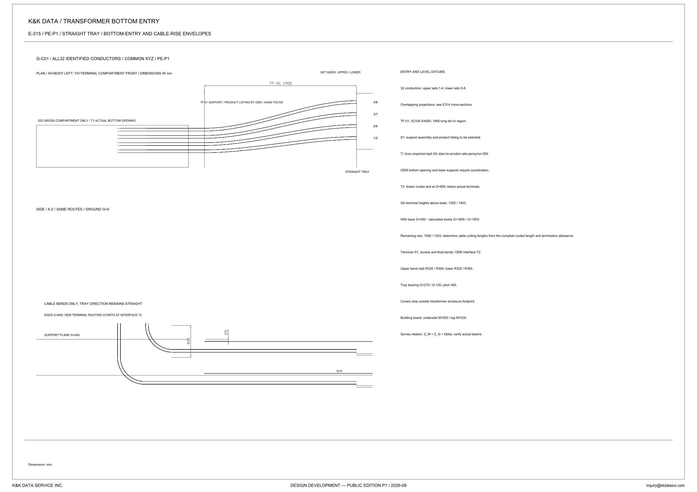
E-315 is the plan and the X-Z side view of the transformer bottom entry. The sheet line reads E-315 / PE-P1 / straight tray / bottom-entry and cable-rise envelopes, and the title block reads Design Development — Public Edition P1 / 2026-09. Dimensions are in mm. The plan states its origin on the view: X0 at the body left, Y0 at the terminal-compartment front. The side view is those same routes, with ground at G=0. The view header names the subject G-C01, all 32 identified conductors, on a common XYZ basis, marked PE-P1. The notes split the 32 conductors into upper sets 1-4 and lower sets 5-8. The plan draws them as four routes tagged, from the top, 4/8, 3/7, 2/6 and 1/5. The note calls that stack overlapping projections and points to the E314 cross-sections. This sheet is the envelope of the straight tray, the fan-in, and the drawn rise.
The compartment, the fan-in, and a tray that stays straight
The rectangle on the left of the plan is labeled 525 gross compartment only, and it names T1 as the actual bottom opening. The note states that depth in words: gross compartment depth 525, with the net bottom cable opening to be obtained from the OEM. The following line says the OEM bottom opening and the base supports require coordination. The routes are drawn through that rectangle and through TF-01. The view dimensions the region TF-01 1900, and the label in it reads TF-01 support / product listing by OEM / X4000 TO2100. The note writes the same region as X2100-X4000, a 1900 long fan-in. S1 says the support assembly and the product listing are to be selected. The plan labels the outer end straight tray. The side-view note says the cables bend only and the tray direction remains straight, so the curves in the plan are the fan-in of the paired routes, and the tray keeps its direction. Covers stop outside the transformer enclosure footprint.
The rise that is drawn only to G+650
The side view draws the support plane at G+450 and is titled SIDE / X-Z / SAME ROUTES / GROUND G=0, and it bends the routes between the horizontal tray runs and the vertical rise. The notes give tray bearings G+270 and G-130 and pitch 400, and the view dimensions that 400 between the runs. A short dimension at the upper run reads 25; that 25 is on the view and is not named in the entry-and-level notes. The callout places the ends at G+650 and says OEM terminal routing starts at interface T2. The T2 note says the drawn routes end at G+650, below the actual terminals, and terminal XY, access and the final bends are OEM interface T2. GA terminal heights above the base are 1200 / 1403. With the base at G+450 the notes give calculated levels G+1650 / G+1853, the base plus each GA height in the printed order. The remaining rise is printed 1000 / 1203. Set against those levels and the drawn end, G+1650 to G+650 is 1000 and G+1853 to G+650 is 1203. No cutting length is printed. The note says to determine cable cutting lengths from the complete routed length and the termination allowance. Upper bend radii are R335 / R300, and the lower bend radii are printed as the same pair.
Status
Published at Design Development — Public Edition P1, with 2026-09 in the title block and PE-P1 on the sheet line: a reference design for study and evaluation. The sheet writes its open items in the notes. S1: the support assembly and the product listing are to be selected, and the TF-01 label reads product listing by OEM. T1: gross compartment depth is 525, the net bottom cable opening is to be obtained from the OEM, and the OEM bottom opening and the base supports require coordination. T2: the drawn routes end at G+650, below the actual terminals, and terminal XY, access and the final bends are OEM interface T2. Cable cutting lengths are to be determined from the complete routed length and the termination allowance. The building board is on datum M, underside M1000 and top M1030. The bearings and the support plane are on datum G. The survey relation is Z_M = Z_G + Delta, with actual beams to be verified. No figure for Delta is given.
Sheet guide — the devices on this drawing
G-C01 — all 32 identified conductors
The plan header reads G-C01 / ALL32 IDENTIFIED CONDUCTORS / COMMON XYZ / PE-P1. The line under it sets the plan origin: X0 at the body left, Y0 at the terminal-compartment front, dimensions in mm. The notes count 32 conductors, upper sets 1-4 and lower sets 5-8, on this common XYZ.
T1 — gross compartment and the actual bottom opening
The plan rectangle is labeled 525 GROSS COMPARTMENT ONLY / T1 ACTUAL BOTTOM OPENING. The note calls 525 the gross compartment depth and says to obtain the net bottom cable opening from the OEM. The next line says the OEM bottom opening and the base supports require coordination.
TF-01 — 1900 mm fan-in, listing by OEM
The fan-in is dimensioned TF-01 1900. Its label reads TF-01 SUPPORT / PRODUCT LISTING BY OEM / X4000 TO2100, and the note writes TF-01 as X2100-X4000, a 1900 long fan-in region. S1 says the support assembly and the product listing are to be selected.
Set index — pairs 4/8, 3/7, 2/6 and 1/5
The heading reads SET INDEX: UPPER / LOWER, and the four routes are tagged 4/8, 3/7, 2/6 and 1/5 from top to bottom, pairing upper sets 1-4 with lower sets 5-8. The note calls the stack overlapping projections and points to the E314 cross-sections. STRAIGHT TRAY is the label at this end of the plan.
Entry and level datums — sets, S1 and T1
The column is headed ENTRY AND LEVEL DATUMS. It states 32 conductors, upper sets 1-4 and lower sets 5-8, and sends the overlapping projections to the E314 cross-sections. It writes TF-01 as X2100-X4000, 1900 long, S1 as the support assembly and product listing to be selected, and T1 as gross compartment depth 525 with the net opening to come from the OEM.
T2 — drawn end G+650 and the two terminal levels
T2 says the drawn routes end at G+650, below the actual terminals, and terminal XY, access and the final bends are OEM interface T2. GA heights above the base are 1200 / 1403; with base G+450 the calculated levels are G+1650 / G+1853, and the remaining rise is 1000 / 1203. Upper and lower bend radii are each printed R335 / R300.
Board and survey — M1000 / M1030 and Delta
Tray bearings are printed G+270 / G-130 with pitch 400, and the covers stop outside the transformer enclosure footprint. The building board is underside M1000 and top M1030. The survey line reads Z_M = Z_G + Delta and says to verify actual beams, with no value of Delta printed.
Side view — cable bends end at G+650
The side view is titled SIDE / X-Z / SAME ROUTES / GROUND G=0. The callouts say the cables bend only, the tray direction remains straight, the ends are at G+650, and OEM terminal routing starts at interface T2. The support plane is drawn at G+450, and the routes bend between the two tray runs and the vertical rise.
Pitch 400 — bearings G+270 and G-130
The side view dimensions 400 between the two horizontal runs, the pitch the notes give with bearings G+270 and G-130. A short dimension at the upper run reads 25, which the entry-and-level notes do not name. G+0 is marked on the lower run.
Get the full drawing set
This sheet is one page of the Electrical Drawing Book — Public Edition P1 (88 pages, 14 MB) — a direct PDF download with a published SHA-256 checksum, no registration. The complete coordinated set is on the downloads page. Background guides: data center one-line diagrams · GB300 NVL72 facility requirements · liquid cooling and CDU design.
Questions about any device or parameter on this sheet: inquiry@kkdatasvc.com or the contact page.