
Data Center Lab · Reference Designs · Electrical
Sheet E-314: How 32 Bottom-Entry Conductors Sit in Two Tray Tiers, and What the Clamp Notes Leave Open
The bottom-entry tray in section: where the 32 conductors sit, which clearance the notes say is not tool space, and which clamp details stay with the supplier and the OEM.
Design Development — Public Edition P1: a reference design for study and evaluation, not a construction issue, not sealed by an Engineer of Record.
Scroll or pinch to zoom, drag to pan, click a highlighted device for its explanation. Vector drawing — it stays sharp at any magnification.
← E-313 · All electrical sheets · E-315 →
What this sheet shows
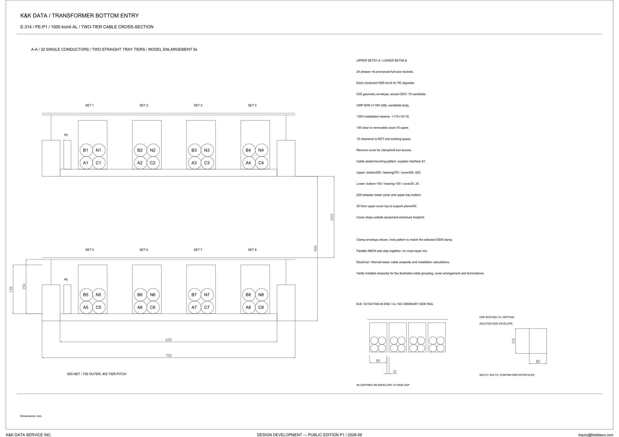
E-314 is the cross-section titled transformer bottom entry. The view heading reads A-A, 32 single conductors, two straight tray tiers, model enlargement 5x, and the sheet states that its dimensions are in mm. The sheet line names the conductors as 1000 kcmil Al. Eight clamps are drawn: SET 1 through SET 4 on the upper tier and SET 5 through SET 8 on the lower tier. In every clamp the upper row is labeled B and N and the lower row A and C, so SET 1 reads B1 and N1 over A1 and C1, and SET 8 reads B8 and N8 over A8 and C8. A PE is labeled outside the clamps, to the left of SET 1 and again to the left of SET 5. The view title says 32 single conductors. The note beside it counts 24 phases and 8 provisional full-size neutrals, and the next line says each conductor is 1000 kcmil Al, with the PE separate.
Widths, pitch and the cover stack
The caption under the section reads 600 net / 700 outer, and a 400 tier pitch. The lower tier carries 600 and 700 as the horizontal dimensions, and 135 and 150 as vertical dimensions at the left. Between the tiers the section dimensions 225. The notes name that 225 as the distance between the lower cover and the upper tray bottom, and they give both tiers as elevations. Upper: bottom 250 / bearing 270 / cover 420..425. Lower: bottom -150 / bearing -130 / cover 20..25. A further line places support plane 450 at 25 from the upper cover top. The cover stops outside the equipment enclosure footprint. Lined up with those elevations, the 150 is the clear distance from the bearing to the cover, the 400 is the pitch from tray bottom to tray bottom, and the 225 is the gap the note names from the lower cover to the upper tray bottom.
Clamp reserve, tool access and the fan-in end
The clamp is given as a candidate body, CMP 80W x 115H x 58L. The installation reserve is written 135H = 115+10+10. The next line is 150 clear to the removable cover, with 15 spare, and the line after that states that the 15 clearance is not tool-working space. The sheet then says to remove the cover for clamp and bolt tool access. The 135 inside the 150 on the lower tier are those two heights. Cable seats and the mounting pattern are supplier interface S1. The clamp envelope is shown; the hole pattern is to match the selected OEM clamp. B-B is the fan-in end, labeled X2100, at model enlargement 3x, and titled no ordinary side rail. It draws four clamps in a row. The spacing note reads 90 centres / 80 envelope / 10 side gap, and the detail dimensions the 80 and the 10. The body is repeated there as 80 x 115, depth 58. The grouping note says parallel ABCN sets stay together, with no cross-layer mix: SET 1 through SET 4 are drawn entirely on the upper tier, and SET 5 through SET 8 entirely on the lower.
Status
Published at Design Development — Public Edition P1 (title block: 2026-09): a reference design for study and evaluation, with the open items written on the sheet. The neutrals are called provisional full-size neutrals. The drawn circle is a D35 geometry envelope, and actual OD31.19 is labeled a candidate. The clamp body is a candidate. Its seats and mounting pattern are supplier interface S1, the hole pattern is to match the selected OEM clamp, and the fan-in view says to confirm OEM interfaces for the seats and bolts. The electrical and thermal basis is named as cable ampacity and installation calculations. No ampacity figure is printed. The note says to verify installed ampacity for the illustrated cable grouping, cover arrangement and terminations.
Sheet guide — the devices on this drawing
SET 1–4 — upper tier ABCN clamps
SET 1 through SET 4 occupy the upper tray. Each clamp is drawn with B and N on the upper row and A and C on the lower row, so SET 1 is B1 and N1 over A1 and C1. The note assigns sets 1-4 to the upper tier and says parallel ABCN sets stay together, with no cross-layer mix. A PE is labeled to the left of SET 1, outside the clamp.
SET 5–8 — lower tier and the 135 / 150
SET 5 through SET 8 repeat the clamp pattern on the lower tier, from B5 and N5 over A5 and C5 through B8 and N8 over A8 and C8. A PE is labeled again beside SET 5. At the left of this tier the section dimensions 135 inside 150, the installation-reserve height and the clear-to-cover dimension named in the clamp notes.
600 net / 700 outer — width and 400 tier pitch
The horizontal dimensions under the lower tier read 600 and 700. The caption calls them 600 net and 700 outer, and states a 400 tier pitch. The sheet says its dimensions are in mm.
225 — lower cover to the upper tray bottom
The vertical dimension in the gap between the tiers reads 225. The note identifies that 225 as the distance between the lower cover and the upper tray bottom. The 400 tier pitch is the taller dimension on the same side of the section.
Notes — 24 phases, D35 envelope, 15 not tool space
The note counts 24 phases and 8 provisional full-size neutrals, and says each conductor is 1000 kcmil Al, with the PE separate. The geometry envelope is D35; actual OD31.19 is a candidate. The reserve is written 135H = 115+10+10, and the clearance is 150 to the removable cover, with 15 spare. The same notes state that the 15 clearance is not tool-working space, and that the cover is removed for clamp and bolt tool access.
Notes — elevations, interface S1, ampacity
Upper elevations read bottom 250, bearing 270, cover 420..425. Lower elevations read bottom -150, bearing -130, cover 20..25. Support plane 450 is 25 from the upper cover top, and the cover stops outside the equipment enclosure footprint. Cable seats and the mounting pattern are supplier interface S1. The basis named is cable ampacity and installation calculations, and the note says to verify installed ampacity for the illustrated grouping, cover arrangement and terminations.
B-B / X2100 — fan-in end, no ordinary side rail
B-B is the fan-in end at X2100, drawn at model enlargement 3x, and titled no ordinary side rail. Four clamps are shown in a row. The spacing note reads 90 centres, an 80 envelope and a 10 side gap, and the detail dimensions the 80 and the 10. The clamp body is repeated as 80 x 115, depth 58.
Isolated envelope — 115 by 80, seats and bolts open
The rectangle beside B-B is labeled an isolated size envelope and is dimensioned 115 high and 80 wide. The line under it says seats and bolts: confirm OEM interfaces. On the main section the companion note says the clamp envelope is shown and the hole pattern is to match the selected OEM clamp.
Get the full drawing set
This sheet is one page of the Electrical Drawing Book — Public Edition P1 (88 pages, 14 MB) — a direct PDF download with a published SHA-256 checksum, no registration. The complete coordinated set is on the downloads page. Background guides: data center one-line diagrams · GB300 NVL72 facility requirements · liquid cooling and CDU design.
Questions about any device or parameter on this sheet: inquiry@kkdatasvc.com or the contact page.