
Data Center Lab · Reference Designs · Electrical
Sheet E-313: Side-Elevation Levels, and Why the Ducts Precede the Piers
The side elevation sets tray and cable-entry levels on datum G, and the sequence puts the MV-P1 ducts and accepted backfill in place before the piers are loaded.
Design Development — Public Edition P1: a reference design for study and evaluation, not a construction issue, not sealed by an Engineer of Record.
Scroll or pinch to zoom, drag to pan, click a highlighted device for its explanation. Vector drawing — it stays sharp at any magnification.
← E-312 · All electrical sheets · E-314 →
What this sheet shows
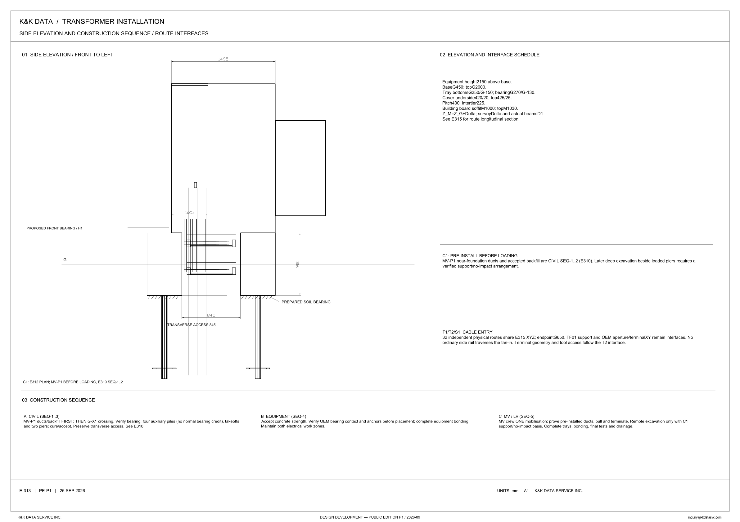
E-313 is the side elevation in the transformer installation set. The sheet title reads side elevation and construction sequence / route interfaces. View 01 is titled side elevation / front to left, so the front of the equipment is the left of this picture. The elevation draws the equipment outline, a vertical group of routes through two tray tiers where the G line crosses the piers, two pier blocks on prepared soil bearing, a pile under each pier, and a further rectangle to the right of the outline. Four dimensions are printed on the picture: 1495 across the upper outline, 525 across the vertical route group, 900 beside the right pier, and 845 on the dimension line between the piles, with transverse access 845 printed under that line. View 02 is the elevation and interface schedule, and that is where the G levels and the M levels are written. Under the schedule, C1 is the pre-install-before-loading note, and T1/T2/S1 is the cable-entry note. Heading 03 is the construction sequence, in blocks A, B and C for civil SEQ-1..3, equipment SEQ-4, and MV/LV SEQ-5. The sheet line reads E-313 | PE-P1 | 26 SEP 2026. Units are mm. The title block reads Design Development — Public Edition P1 / 2026-09.
Elevations on G, and the building on M
View 02 is the elevation and interface schedule, read in the order printed. Equipment height is 2150 above the base. The base is G450 and the top is G2600. Tray bottoms are G250 and G-150, so one bottom is above datum G and the other is below it, and the elevation draws two tray tiers where that line crosses the piers. Bearings are G270 and G-130. Cover underside is printed 420/20 and cover top is printed 425/25. Those cover figures do not carry the G prefix used on the tray bottoms and the bearings, and the line does not name which tier each figure belongs to. The line after the cover figures prints pitch 400, paired with intertier 225. The building board leaves datum G: soffit M1000, top M1030. The next line prints Z_M = Z_G + Delta; survey Delta and actual beams D1. No value of Delta is printed. The route longitudinal section is E315.
The sequence, and what C1 is doing
Heading 03 is the construction sequence, set below the rule under the elevation. The C1 pre-install note is under the elevation schedule, and the T1 cable-entry note is on the right between that note and the sequence rule. The callout under the piles, C1: E312 plan, sits above heading 03. C1 places the MV-P1 near-foundation ducts and the accepted backfill at civil SEQ-1..2, referenced to E310. Later deep excavation beside loaded piers requires a verified support/no-impact arrangement. Block A is civil, SEQ-1..3: MV-P1 ducts and backfill first, then the G-X1 crossing, then verify the bearing. The same sentence names four auxiliary piles, with no normal bearing credit, the takeoffs and two piers, then cure/accept, and it says to preserve transverse access. The elevation labels that access 845. The side view draws a pile under each of the two piers, ending in a short cross-bar. The four auxiliary piles are the count in the sentence. The callout under the piers reads C1: E312 plan, MV-P1 before loading, E310 SEQ-1..2. Block B is equipment, SEQ-4: accept concrete strength, verify OEM bearing contact and anchors before placement, complete equipment bonding, and maintain both electrical work zones. Block C is MV/LV, SEQ-5. The MV crew has one mobilisation: prove the pre-installed ducts, pull and terminate. Remote excavation only with the C1 support/no-impact basis. Then complete the trays, bonding, final tests and drainage.
Status
The sheet is published at Design Development — Public Edition P1. The title block carries 2026-09, and the sheet line reads E-313 | PE-P1 | 26 SEP 2026. It is a reference design for study and evaluation. The open items are the ones the sheet names. The schedule prints Z_M = Z_G + Delta; survey Delta and actual beams D1. The front bearing is labeled proposed front bearing / H1, and no level for H1 is printed. T1/T2/S1 states 32 independent physical routes sharing the E315 XYZ, with the endpoint at G650. TF01 support and the OEM aperture and terminal XY remain interfaces. No ordinary side rail traverses the fan-in. Terminal geometry and tool access follow the T2 interface. Later deep excavation beside loaded piers is stated as a requirement for a verified support/no-impact arrangement. The four auxiliary piles are stated with no normal bearing credit. The route longitudinal section is E315, and the plan named in the C1 callout is E312. Units are mm.
Sheet guide — the devices on this drawing
Equipment outline — 1495 across the top
View 01 is the side elevation, front to the left. The dimension 1495 is printed across the upper equipment outline. The schedule reads the same equipment as height 2150 above the base, with the base at G450 and the top at G2600.
H1 — proposed front bearing
The leader on the left is labeled proposed front bearing / H1, on the side the view title calls the front. The word proposed is part of the label. The schedule prints no level for H1.
G — tray tiers and the vertical routes
The G line runs through the pier zone, and two tray tiers are drawn there, with the vertical routes dropping through. The elevation prints 525 across that vertical route group. Tray bottoms, bearings, pitch and intertier are in the schedule. The cable-entry note sets the endpoint at G650.
Piers — prepared soil bearing, access 845
Two pier blocks sit on the hatched prepared soil bearing. A vertical dimension of 900 is printed beside the right pier. The elevation draws a pile under each pier, ending in a short cross-bar, and it dimensions transverse access as 845 in the gap. The civil sentence states four auxiliary piles, with no normal bearing credit, together with takeoffs and two piers.
C1 callout — MV-P1 before loading
The line under the piers reads C1: E312 plan, MV-P1 before loading, E310 SEQ-1..2. It points this elevation at the plan on E312 and at the civil pre-install on E310. The full wording of the pre-install rule is the C1 note on the right.
02 — elevation and interface schedule
View 02 prints the levels. Equipment height is 2150 above the base, the base is G450 and the top is G2600. Tray bottoms are G250 and G-150, bearings are G270 and G-130, cover underside is 420/20 and cover top is 425/25, pitch is 400 and intertier is 225. The cover figures do not carry the G prefix used on the bottoms and the bearings. Building board soffit is M1000 and top is M1030. Z_M = Z_G + Delta; survey Delta and actual beams D1. The longitudinal section is E315.
C1 — pre-install before loading
C1 is titled pre-install before loading. It places the MV-P1 near-foundation ducts and the accepted backfill at civil SEQ-1..2, referenced to E310. Later deep excavation beside loaded piers requires a verified support/no-impact arrangement.
T1/T2/S1 — cable entry
The cable-entry note is headed T1/T2/S1. It states 32 independent physical routes sharing the E315 XYZ, with the endpoint at G650. TF01 support and the OEM aperture and terminal XY remain interfaces. No ordinary side rail traverses the fan-in. Terminal geometry and tool access follow the T2 interface.
A — civil SEQ-1..3
Block A is civil work, SEQ-1..3. MV-P1 ducts and backfill come first, then the G-X1 crossing. Verify the bearing. The sentence names four auxiliary piles with no normal bearing credit, the takeoffs and two piers, then cure/accept. Preserve transverse access. See E310.
B and C — SEQ-4 equipment, SEQ-5 MV/LV
Block B is equipment, SEQ-4: accept concrete strength, verify OEM bearing contact and anchors before placement, complete equipment bonding, and maintain both electrical work zones. Block C is MV/LV, SEQ-5: the MV crew in one mobilisation, to prove the pre-installed ducts, pull and terminate. Remote excavation only with the C1 support/no-impact basis. Then trays, bonding, final tests and drainage.
Get the full drawing set
This sheet is one page of the Electrical Drawing Book — Public Edition P1 (88 pages, 14 MB) — a direct PDF download with a published SHA-256 checksum, no registration. The complete coordinated set is on the downloads page. Background guides: data center one-line diagrams · GB300 NVL72 facility requirements · liquid cooling and CDU design.
Questions about any device or parameter on this sheet: inquiry@kkdatasvc.com or the contact page.