
Data Center Lab · Reference Designs · Electrical
Sheet E-312: Coordinated Envelopes — What 1900, 1495, 2220, and the Front-Compartment 525 Each Mean
The plan prints four lengths a reader can mix up, 1900, 2200, 1495 and 2220, and the note says the front compartment's 525 is not a net cable aperture, while TF01 on X2100..4000 remains product detail by the OEM.
Design Development — Public Edition P1: a reference design for study and evaluation, not a construction issue, not sealed by an Engineer of Record.
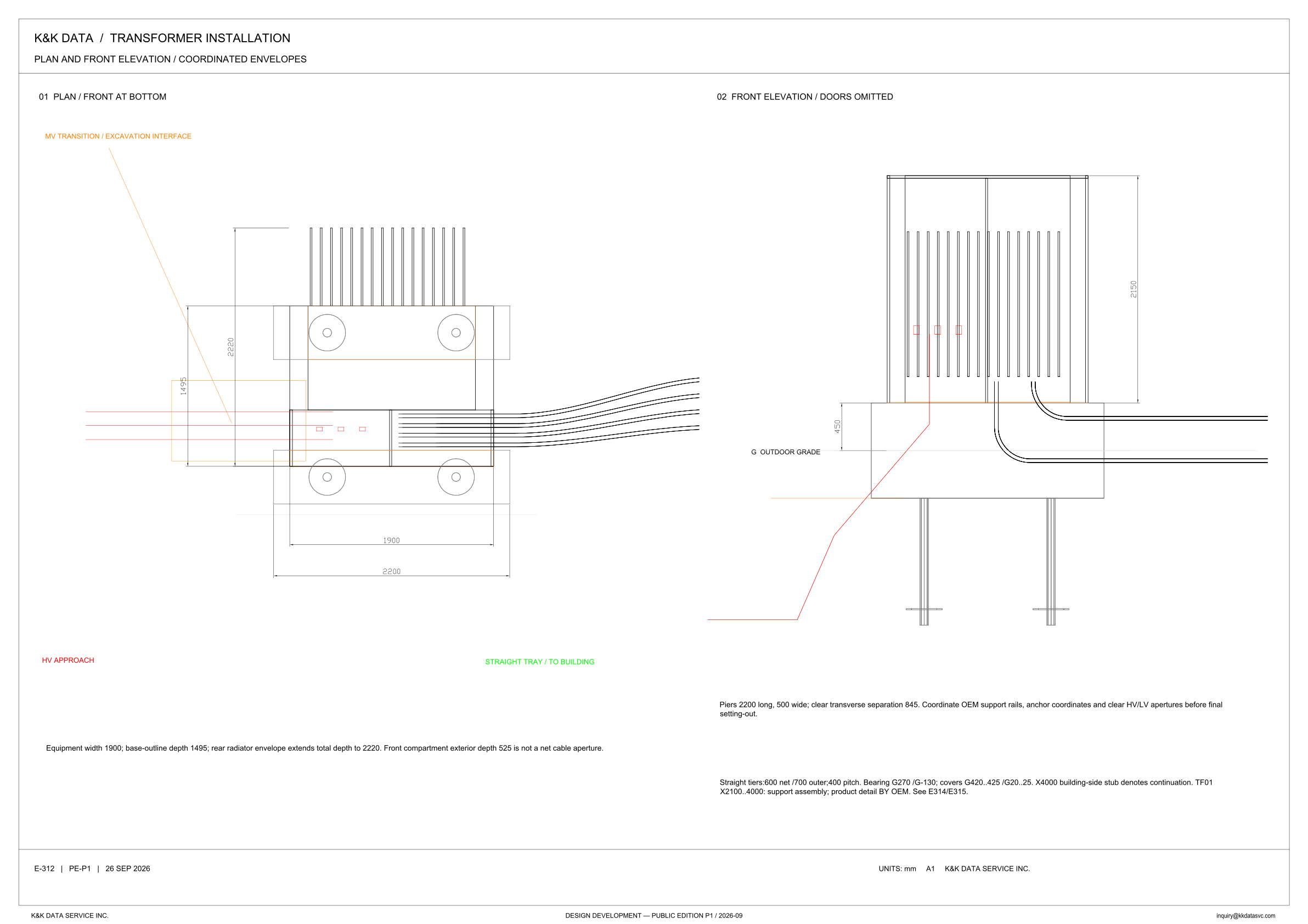
Scroll or pinch to zoom, drag to pan, click a highlighted device for its explanation. Vector drawing — it stays sharp at any magnification.
← E-311 · All electrical sheets · E-313 →
What this sheet shows
E-312 is the plan and front elevation in the transformer installation set, headed plan and front elevation / coordinated envelopes. View 01 is the plan, and the view title places the front at the bottom. View 02 is the front elevation, and its title says the doors are omitted. With the front at the bottom, the radiator bank drawn above the tank is the rear bank named in the envelope note. The plan draws the HV approach in red into the front compartment, labels the straight tray to the building in green, and draws an orange line labeled MV transition / excavation interface. The elevation looks at that same front: it prints 2150 on the tank, labels the grade G outdoor grade, prints 450 beside the pier, draws two piles below the pier, and shows the tray cables leaving the tank and turning out to the side. The sheet line reads E-312 | PE-P1 | 26 SEP 2026, units are mm, and the title block reads Design Development — Public Edition P1 / 2026-09.
Width, depth, and the pier hold
The note under the plan separates the outlines. Equipment width is 1900, and the plan prints 1900 across the tank. Base-outline depth is 1495, and the plan prints 1495 for that outline. The rear radiator envelope extends the total depth to 2220, and the plan prints 2220 across the depth that includes the radiator bank. The 1495 is the base. The 2220 is the base once the rear radiators are counted in. Along the width, the pier runs past the tank. The note gives the piers as 2200 long and 500 wide, with a clear transverse separation of 845, and the plan prints 2200 under the front pier, past the 1900 equipment width. The following sentence keeps the next figure from being used as an opening. Front compartment exterior depth 525 is not a net cable aperture. The plan draws the HV approach into that compartment and draws three small squares there, and the elevation repeats the three squares. The same pier note is the hold on setting-out: coordinate OEM support rails, anchor coordinates and clear HV/LV apertures before final setting-out.
Straight tiers and TF01
Under the elevation, the straight-tier note reads 600 net / 700 outer, with 400 pitch. It then states bearings G270 / G-130 and covers G420..425 / G20..25. The elevation is where G is named, as G outdoor grade, and the note uses that G for both the bearings and the covers. It prints the two bearings and the two cover ranges in that order and does not name which tier each figure belongs to. An X4000 building-side stub denotes continuation. The plan labels the run, in green, straight tray / to building. On the plan that tray leaves the front of the tank toward the right of the sheet, and the HV approach is drawn into the left of that same front. TF01 is the support assembly for X2100..4000. The product detail is by the OEM, and the note points to E314/E315.
Status
Published at Design Development — Public Edition P1. The title block carries 2026-09, and the sheet line reads E-312 | PE-P1 | 26 SEP 2026. This is a reference design for study and evaluation. The open coordination is printed on the sheet. OEM support rails, anchor coordinates and clear HV/LV apertures are to be coordinated before final setting-out. The plan draws two circular marks on each pier. Those marks are not labeled as the finished anchor coordinates. The sentence that names the coordinates is the coordination still to be done. TF01, for X2100..4000, carries the words product detail by the OEM, and the note refers that detail to E314/E315. Front compartment exterior depth 525 is not a net cable aperture. View 02 omits the doors, and that statement belongs to the view. Drawing units are mm.
Sheet guide — the devices on this drawing
01 — plan, front at the bottom
View 01 is the plan, and the title places the front at the bottom of the sheet. The radiator bank is drawn on the opposite side of that front, which the envelope note calls the rear. Depths on this view read with that orientation: 1495 for the base outline, and 2220 once the rear radiator envelope is included.
Plan envelopes — 1900, 1495, and 2220
The plan prints 1900 across the tank, 1495 on the base outline, and 2220 across the depth that includes the radiator bank. The note assigns those three figures: equipment width 1900, base-outline depth 1495, and a rear radiator envelope that extends the total depth to 2220. The next sentence keeps 525 as the front compartment exterior depth, and states that it is not a net cable aperture.
HV approach — front compartment
Red lines enter the front compartment from the left of the plan. The label under the view reads HV approach. Three small squares sit in that compartment, and the elevation repeats them. The envelope note says the front compartment exterior depth of 525 is not a net cable aperture, and the pier note still asks for the clear HV/LV apertures to be coordinated before final setting-out.
Straight tray — to the building
A bundle of lines leaves the front of the tank toward the right of the plan. The green label under the view reads straight tray / to building. The note under the elevation gives that run as straight tiers, 600 net / 700 outer, with 400 pitch, and an X4000 building-side stub that denotes continuation.
Piers — 2200 long, separation 845
The plan draws two piers, one at the front and one toward the rear, each with two circular marks. It prints 2200 under the front pier. The note states the piers as 2200 long and 500 wide, with a clear transverse separation of 845, and it says to coordinate OEM support rails, anchor coordinates and clear HV/LV apertures before final setting-out.
02 — front elevation, doors omitted
View 02 is the front elevation, and the title says the doors are omitted. The tank carries a vertical dimension of 2150. Three small squares sit toward the HV-approach side, a run of vertical lines crosses the rest of the face, and the tray cables leave the tank, turn down, and run out to the side. The omitted doors are a statement about this view.
G outdoor grade — 450 beside the pier
The elevation labels the grade line G outdoor grade and prints 450 beside the pier at that line. Two piles are drawn below the pier. The tray note uses the same G for bearings G270 / G-130 and for covers G420..425 / G20..25. This view is where that datum is named.
MV transition / excavation interface
An orange line on the plan is labeled MV transition / excavation interface, and it runs down to the front compartment where the HV approach enters. The elevation draws a line up from below the pier to the three squares. The label is what this sheet says about that interface.
Setting-out — rails, anchors, apertures
The pier note is the setting-out hold. Piers are 2200 long and 500 wide, with a clear transverse separation of 845. OEM support rails, anchor coordinates and clear HV/LV apertures are to be coordinated before final setting-out. The circular marks on the piers are drawn. The coordinates themselves remain the coordination this sentence names.
TF01 — support assembly X2100..4000
Straight tiers are given as 600 net / 700 outer, with 400 pitch. Bearings are G270 / G-130, and covers are G420..425 / G20..25. An X4000 building-side stub denotes continuation. TF01 on X2100..4000 is the support assembly, and the product detail is by the OEM. The note points that detail to E314/E315.
Get the full drawing set
This sheet is one page of the Electrical Drawing Book — Public Edition P1 (88 pages, 14 MB) — a direct PDF download with a published SHA-256 checksum, no registration. The complete coordinated set is on the downloads page. Background guides: data center one-line diagrams · GB300 NVL72 facility requirements · liquid cooling and CDU design.
Questions about any device or parameter on this sheet: inquiry@kkdatasvc.com or the contact page.