
Data Center Lab · Reference Designs · Electrical
Sheet E-311: The Transformer on Two Concrete Piers, Prepared Soil Beneath Both, with 32 Routes Stopping at G650
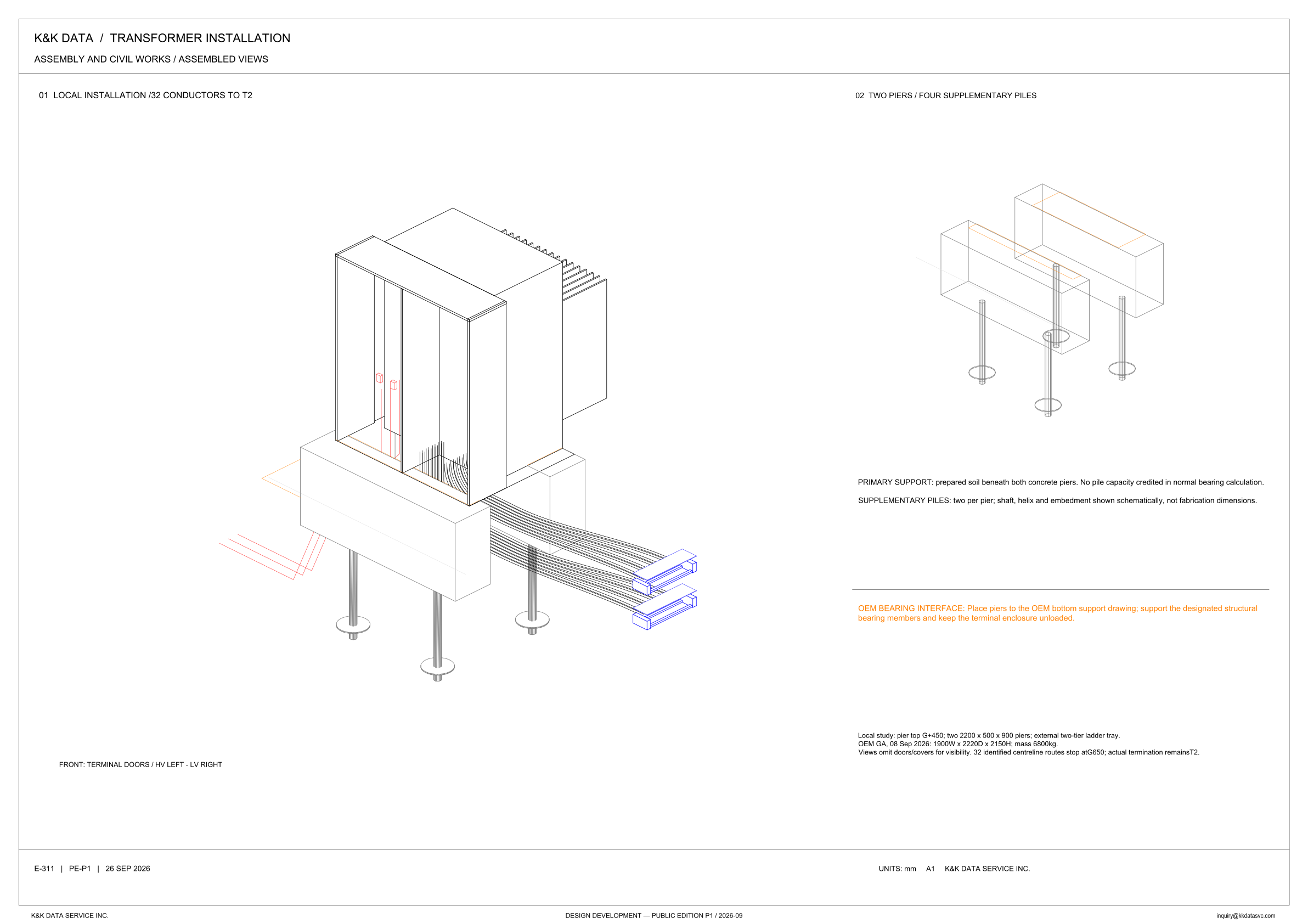
View 01 puts the transformer on two concrete piers, prepared soil beneath both, and view 02 draws those piers and four supplementary piles with no transformer body, while the notes credit no pile capacity in the normal bearing calculation, keep the terminal enclosure unloaded, and stop 32 centreline routes at G650 while termination remains at T2.
Design Development — Public Edition P1: a reference design for study and evaluation, not a construction issue, not sealed by an Engineer of Record.
Scroll or pinch to zoom, drag to pan, click a highlighted device for its explanation. Vector drawing — it stays sharp at any magnification.
← E-310 · All electrical sheets · E-312 →
What this sheet shows
E-311 is the assembled-view sheet in the transformer installation set. The heading reads assembly and civil works / assembled views, and the sheet carries two pictures. View 01 is the local installation, titled 32 conductors to T2: the transformer on its piers, with the conductor bundle drawn out to the right. The label under that view defines the front as terminal doors, HV left and LV right, and the local-study note says the views omit doors and covers for visibility. View 02 is titled two piers / four supplementary piles, and it draws the piers and piles without the transformer body. Notes under view 02 state the primary support and the way the piles are shown. The same column continues downward: a rule, then the orange OEM bearing interface. The local-study line records pier top G+450, two 2200 x 500 x 900 piers, and the external two-tier ladder tray. The next line reads OEM GA, 08 Sep 2026: 1900W x 2220D x 2150H; mass 6800kg. The sheet line reads E-311 | PE-P1 | 26 SEP 2026, drawing units are mm, and the title block reads Design Development — Public Edition P1 / 2026-09.
Prepared soil, schematic piles, unloaded enclosure
Primary support is prepared soil beneath both concrete piers. No pile capacity is credited in normal bearing calculation. The piles are supplementary: the view 02 title says four supplementary piles, and the note says two per pier. Shaft, helix and embedment are shown schematically, not fabrication dimensions. The orange note is the OEM bearing interface, and it is written as an instruction. Place piers to the OEM bottom support drawing. Support the designated structural bearing members. Keep the terminal enclosure unloaded. The front label on view 01 reads terminal doors, HV left and LV right. The local study sets pier top G+450 and calls for two piers of 2200 x 500 x 900. It prints those three figures without naming width, depth or height. The labeled envelope is the OEM line, from the GA of 08 Sep 2026: 1900W x 2220D x 2150H, mass 6800kg.
32 routes stop at G650; termination remains T2
The view 01 title says 32 conductors to T2. The local-study note separates the lines that are drawn from the place where the conductors terminate. It identifies 32 centreline routes, and those routes stop at G650. Actual termination remains T2. The title names the destination; the note stops the identified centrelines at G650 and leaves the termination at T2. The bundle is drawn on the right, the side the front label calls LV, and it runs out to the external two-tier ladder tray named in the same local study. Lines are drawn on the left as well, the HV terminal-door side, and the sheet gives those lines no separate name. Doors and covers are omitted for visibility. That sentence is about the view. The sheet does not say the covers are absent from the assembly.
Status
The sheet is published at Design Development — Public Edition P1. The title block carries 2026-09, and the sheet line reads E-311 | PE-P1 | 26 SEP 2026. It is a reference design for study and evaluation. The limits are printed on the drawing. Pile shaft, helix and embedment are schematic, not fabrication dimensions, and no pile capacity is credited in normal bearing calculation. Piers are to be placed to the OEM bottom support drawing, the designated structural bearing members are the support the note names, and the terminal enclosure is to be kept unloaded. The OEM GA of 08 Sep 2026 states 1900W x 2220D x 2150H and mass 6800kg. Of the conductors, 32 identified centreline routes stop at G650, and actual termination remains T2. Drawing units are mm.
Sheet guide — the devices on this drawing
01 — local installation, 32 conductors to T2
View 01 is titled local installation / 32 conductors to T2. The picture is the transformer on the piers, with the conductor bundle drawn out to the side. Read it with the local-study note: 32 identified centreline routes stop at G650, and actual termination remains T2.
Transformer body — doors and covers omitted
The assembled view draws the transformer body with the terminal compartments open. The sheet says the views omit doors and covers for visibility, so the open interior is the drawing convention on this sheet. The OEM GA dated 08 Sep 2026 states the envelope as 1900W x 2220D x 2150H and the mass as 6800kg.
Piers and piles — under the assembled unit
View 01 shows the concrete piers under the transformer and the supplementary piles below them, each pile drawn with a shaft and a helix. View 02 titles the same support as two piers / four supplementary piles, and the note says two per pier. Shaft, helix and embedment are schematic, not fabrication dimensions, and no pile capacity is credited in normal bearing calculation.
Two-tier tray — 32 centreline routes
The conductor bundle is drawn on the right of view 01 and runs to the external two-tier ladder tray. The local study names that tray. The same note identifies 32 centreline routes, stops them at G650, and says actual termination remains T2. The view 01 title names that destination as 32 conductors to T2.
Front — terminal doors, HV left, LV right
The label defines the front of view 01 as terminal doors, with HV on the left and LV on the right. The conductor bundle sits on the right, the LV side. Lines are drawn on the left, the HV terminal-door side, and the sheet does not give those lines a further name.
02 — two piers and four supplementary piles
View 02 draws the two piers alone, with four supplementary piles and a line along the top of each pier. The note under the view says two per pier, and it says the shaft, helix and embedment are shown schematically, not fabrication dimensions. Primary support is prepared soil beneath both concrete piers.
Primary support — prepared soil, no pile credit
Primary support is prepared soil beneath both concrete piers. No pile capacity is credited in normal bearing calculation. The supplementary piles are two per pier, and their shaft, helix and embedment are shown schematically, not fabrication dimensions.
OEM bearing interface — enclosure kept unloaded
The orange note is the OEM bearing interface. Place piers to the OEM bottom support drawing, support the designated structural bearing members, and keep the terminal enclosure unloaded. This sheet states that interface and does not reproduce the OEM bottom support drawing.
Local study — G+450, pier size, OEM GA, G650
Pier top is G+450. The study calls for two 2200 x 500 x 900 piers and an external two-tier ladder tray, and it does not name the three pier figures as width, depth or height. The OEM GA of 08 Sep 2026 is 1900W x 2220D x 2150H, mass 6800kg. Views omit doors and covers for visibility. 32 identified centreline routes stop at G650; actual termination remains T2.
E-311 — PE-P1, 26 SEP 2026
The lower sheet line reads E-311 | PE-P1 | 26 SEP 2026. That line carries the sheet number, the PE-P1 mark, and the date together. It is the identification line for this assembled-views sheet.
Get the full drawing set
This sheet is one page of the Electrical Drawing Book — Public Edition P1 (88 pages, 14 MB) — a direct PDF download with a published SHA-256 checksum, no registration. The complete coordinated set is on the downloads page. Background guides: data center one-line diagrams · GB300 NVL72 facility requirements · liquid cooling and CDU design.
Questions about any device or parameter on this sheet: inquiry@kkdatasvc.com or the contact page.