
Data Center Lab · Reference Designs · Electrical
Sheet E-310: Accept the MV-P1 Backfill Before Foundation Loading
MV-P1 ducts go in and the backfill is accepted before foundation loading, S is determined from the bearing and excavation geometry, and SEQ-5 writes the MV crew as one mobilisation.
Design Development — Public Edition P1: a reference design for study and evaluation, not a construction issue, not sealed by an Engineer of Record.
Scroll or pinch to zoom, drag to pan, click a highlighted device for its explanation. Vector drawing — it stays sharp at any magnification.
← E-309 · All electrical sheets · E-311 →
What this sheet shows
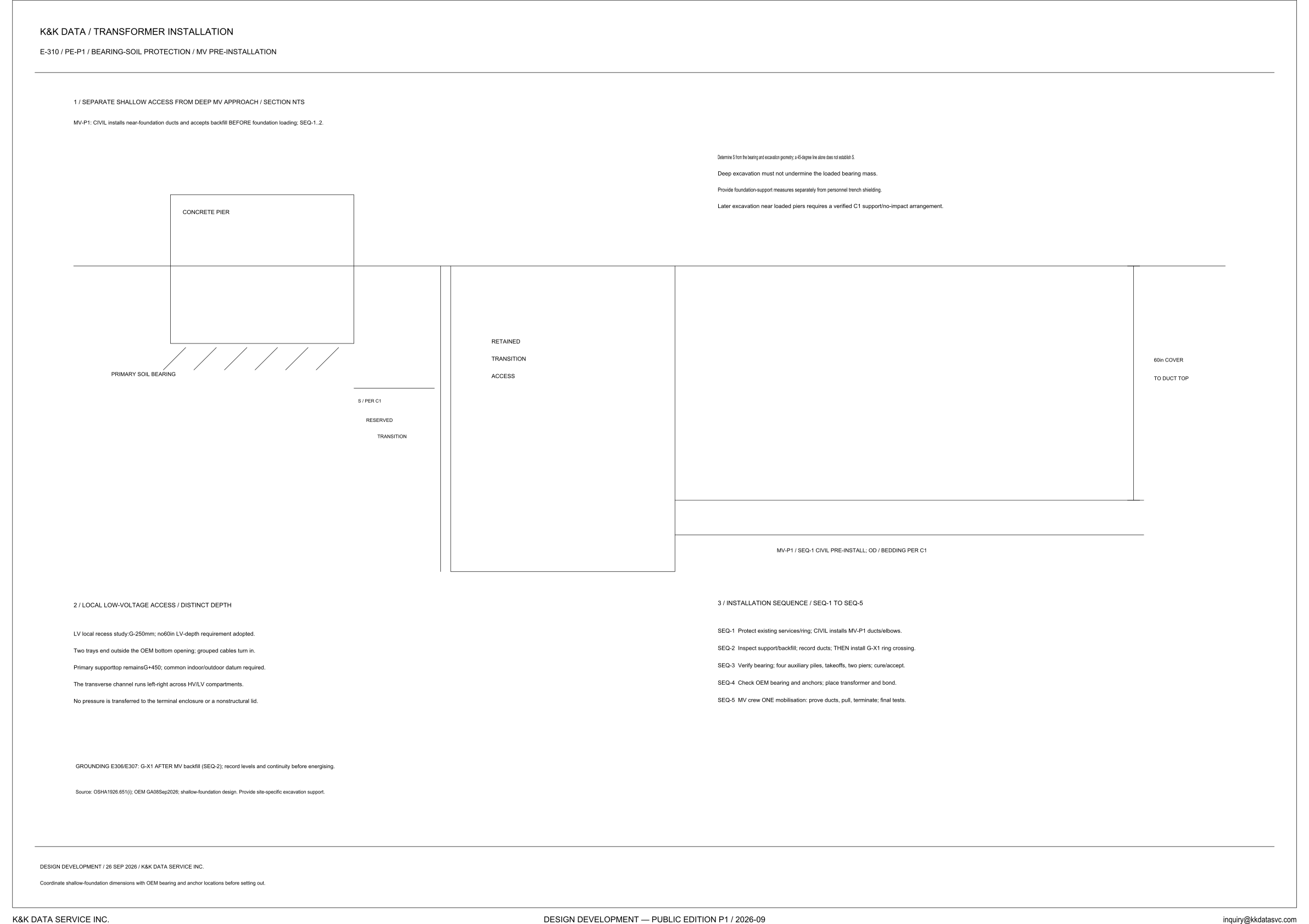
E-310 is the bearing-soil protection / MV pre-installation sheet in the transformer-installation set. Heading 1 is a section marked NTS, titled separate shallow access from the deep MV approach. Heading 2 is the local low-voltage access at a distinct depth. Heading 3 is the installation sequence from SEQ-1 to SEQ-5. The sheet line reads E-310 / PE-P1 / BEARING-SOIL PROTECTION / MV PRE-INSTALLATION. The margin line reads Design Development / 26 SEP 2026 / K&K DATA SERVICE INC., and the title block reads Design Development — Public Edition P1 / 2026-09. Across the section the order is a concrete pier, hatched primary soil bearing beneath the pier, a reserved zone capped S / PER C1, a zone carrying the words retained, transition, and access, and the deep MV-P1 run. That run is labeled MV-P1 / SEQ-1 CIVIL PRE-INSTALL; OD / BEDDING PER C1, and the right-hand column reads 60in cover to duct top. The line under heading 1 states the timing: MV-P1 civil installs the near-foundation ducts and accepts backfill before foundation loading, at SEQ-1..2.
Shallow bearing and the deep approach
Heading 1 separates shallow access from the deep MV approach, and the section draws them as different zones. The reserved zone beside the bearing is capped S / PER C1, and the sheet prints no length for S. The note above the section says to determine S from the bearing and excavation geometry; a 45-degree line alone does not establish S. The next zone carries the stacked words retained, transition, and access. On the deep side the column states 60in cover to duct top, and the run is the SEQ-1 civil pre-install, with OD and bedding per C1 and no duct size on the label. Deep excavation must not undermine the loaded bearing mass. The bearing drawn under the pier is the hatched primary soil bearing. Foundation-support measures are to be provided separately from personnel trench shielding. Later excavation near loaded piers requires a verified C1 support/no-impact arrangement. The line under heading 1 places the MV-P1 ducts and the backfill acceptance at SEQ-1..2, before foundation loading.
Distinct LV depth and the installation sequence
Heading 2 keeps the local low-voltage access at a distinct depth. The recess is an LV local recess study at G-250mm, and no 60in LV-depth requirement is adopted. Two trays end outside the OEM bottom opening; grouped cables turn in. The primary support top remains G+450, and a common indoor/outdoor datum is required. The transverse channel runs left-right across the HV/LV compartments. No pressure is transferred to the terminal enclosure or a nonstructural lid. The 60in figure on the section is the cover to the MV duct top, and the LV note has no 60in LV-depth requirement adopted. The recess remains a study at G-250mm. Heading 3 is the sequence from SEQ-1 to SEQ-5. SEQ-1 protects existing services/ring; civil installs the MV-P1 ducts and elbows. SEQ-2 inspects the support and backfill, records the ducts, and then installs the G-X1 ring crossing. SEQ-3 verifies the bearing and includes four auxiliary piles, takeoffs, and two piers, with cure/accept. SEQ-4 checks OEM bearing and anchors, then places the transformer and bond. SEQ-5 is one MV-crew mobilisation: prove the ducts, pull, terminate, and final tests. The grounding line places G-X1 AFTER MV backfill at SEQ-2, and it requires levels and continuity to be recorded before energising. The grounding reference on that line is E306/E307.
Status
Published at Design Development — Public Edition P1 (title block: 2026-09; margin line: 26 SEP 2026). This is a reference design for study and evaluation. The section is marked NTS. The length of S is per C1, and a 45-degree line alone does not establish S. OD and bedding are per C1. Shallow-foundation dimensions are to be coordinated with OEM bearing and anchor locations before setting out, and those coordinated dimensions are not printed here. The LV local recess is a study at G-250mm. Later excavation near loaded piers requires a verified C1 support/no-impact arrangement. The source line names OSHA1926.651(i), OEM GA08Sep2026, and shallow-foundation design, and it says to provide site-specific excavation support. Foundation-support measures are stated separately from personnel trench shielding.
Sheet guide — the devices on this drawing
MV-P1 — backfill before foundation loading
Heading 1 separates shallow access from the deep MV approach, and the section is marked NTS. The line under it gives the order for MV-P1: civil installs the near-foundation ducts and accepts backfill before foundation loading, at SEQ-1..2.
Concrete pier — primary soil bearing
The shallow-side rectangle is labeled concrete pier. The hatching beneath it is labeled primary soil bearing. No bearing-pressure value is printed on this sheet; the protection notes refer to the loaded bearing mass.
S / PER C1 — reserved transition
Beside the bearing, the section marks a reserved zone. Its cap reads S / PER C1, with the words reserved and transition under that note, and no length for S is printed. Determine S from the bearing and excavation geometry; a 45-degree line alone does not establish S.
Retained transition access
The tall zone between the reserved transition and the deep MV run carries the stacked words retained, transition, and access. It is the labeled separation between the shallow bearing side and the deep approach. The sheet prints no width for this zone.
MV-P1 — 60in cover to duct top
The right-hand column reads 60in cover to duct top. The run below is labeled MV-P1 / SEQ-1 CIVIL PRE-INSTALL; OD / BEDDING PER C1. The cover is stated; OD and bedding are referred to C1, and the label prints no duct size.
Excavation notes — S, bearing mass, shielding
Four notes sit above the deep approach. S is determined from the bearing and excavation geometry, and a 45-degree line alone does not establish S. Deep excavation must not undermine the loaded bearing mass, foundation-support measures are provided separately from personnel trench shielding, and later excavation near loaded piers requires a verified C1 support/no-impact arrangement.
LV recess — G-250mm distinct depth
Heading 2 is the local low-voltage access at a distinct depth. It is an LV local recess study at G-250mm, and no 60in LV-depth requirement is adopted; the primary support top remains G+450, with a common indoor/outdoor datum required. Two trays end outside the OEM bottom opening and the grouped cables turn in, the transverse channel runs left-right across the HV/LV compartments, and no pressure is transferred to the terminal enclosure or a nonstructural lid.
SEQ-1 to SEQ-5 — installation sequence
SEQ-1 protects existing services/ring; civil installs the MV-P1 ducts and elbows. SEQ-2 inspects the support and backfill, records the ducts, and then installs the G-X1 ring crossing; SEQ-3 verifies the bearing and includes four auxiliary piles, takeoffs, and two piers, with cure/accept. SEQ-4 checks OEM bearing and anchors, then places the transformer and bond; SEQ-5 is one MV-crew mobilisation to prove the ducts, pull, terminate, and final tests.
G-X1 — ring crossing after MV backfill
The grounding line reads GROUNDING E306/E307: G-X1 AFTER MV backfill (SEQ-2), and it requires levels and continuity to be recorded before energising. SEQ-2 is where the sheet installs the G-X1 ring crossing, after the support and backfill are inspected and the ducts are recorded. The source line names OSHA1926.651(i), OEM GA08Sep2026, and shallow-foundation design, and it says to provide site-specific excavation support.
Setting out — OEM bearing and anchors
The lower margin says to coordinate shallow-foundation dimensions with OEM bearing and anchor locations before setting out. The same margin dates the sheet Design Development / 26 SEP 2026. The coordinated dimensions are not printed on this sheet.
Get the full drawing set
This sheet is one page of the Electrical Drawing Book — Public Edition P1 (88 pages, 14 MB) — a direct PDF download with a published SHA-256 checksum, no registration. The complete coordinated set is on the downloads page. Background guides: data center one-line diagrams · GB300 NVL72 facility requirements · liquid cooling and CDU design.
Questions about any device or parameter on this sheet: inquiry@kkdatasvc.com or the contact page.