
Data Center Lab · Reference Designs · Electrical
Sheet E-309: Normal Vertical Support on Two Prepared-Soil Piers, Piles at Zero Capacity Credit
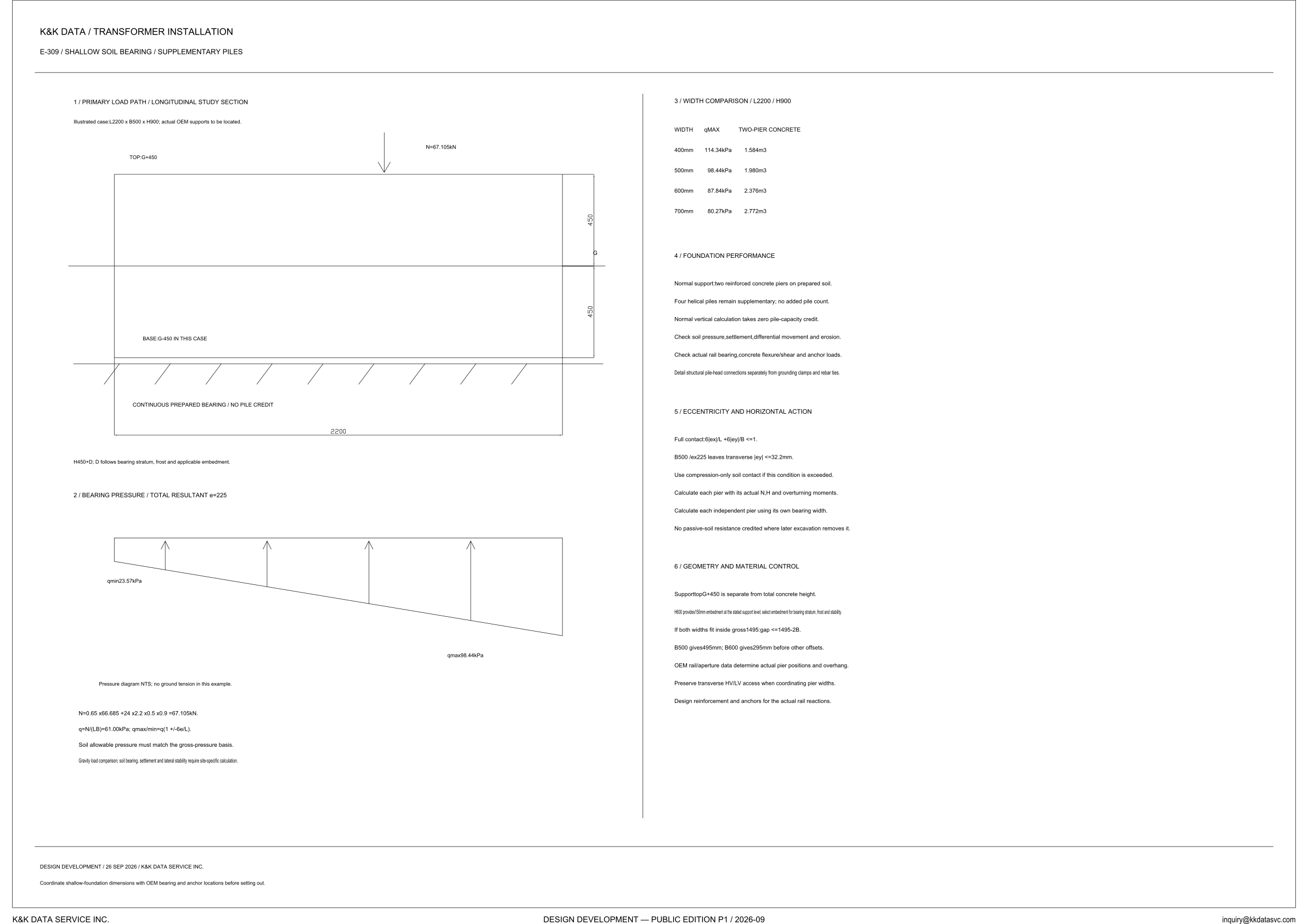
The normal vertical calculation stands on two reinforced concrete piers and prepared soil, four helical piles remain supplementary at zero pile-capacity credit, and the illustrated B500 case states qmax 98.44 kPa.
Design Development — Public Edition P1: a reference design for study and evaluation, not a construction issue, not sealed by an Engineer of Record.
Scroll or pinch to zoom, drag to pan, click a highlighted device for its explanation. Vector drawing — it stays sharp at any magnification.
← E-307 · All electrical sheets · E-310 →
What this sheet shows
E-309 is the shallow-soil-bearing sheet in the transformer-installation set, titled shallow soil bearing / supplementary piles. Heading 1 is a longitudinal study section of the pier. Heading 2 is the bearing-pressure diagram for the total resultant. Heading 3 compares pier widths at L2200 / H900. Heading 4 states foundation performance. Heading 5 is the full-contact test. Heading 6 controls geometry and materials. The margin line reads Design Development / 26 SEP 2026 / K&K DATA SERVICE INC., and the title block reads Design Development — Public Edition P1 / 2026-09. The line under heading 1 states the limit of the picture: illustrated case L2200 × B500 × H900, with the actual OEM supports still to be located.
Illustrated pier and bearing pressure
The study section marks the support top at G+450 and the base at G-450 in this case, and it dimensions 450 above grade G and 450 below it. The downward arrow is labeled N=67.105 kN. The band under the pier is labeled continuous prepared bearing / no pile credit, and the length under that band is 2200. The note at the band reads H450+D, with D following the bearing stratum, frost and applicable embedment. Heading 2 is titled bearing pressure / total resultant e=225. The diagram is NTS, and it states no ground tension in this example. qmin at the left edge is 23.57 kPa and qmax at the right edge is 98.44 kPa. The lines under the figure write the gravity-load comparison: N=0.65 × 66.685 + 24 × 2.2 × 0.5 × 0.9 = 67.105 kN, then q=N/(LB)=61.00 kPa, and qmax/min=q(1 ± 6e/L). The factors 2.2, 0.5 and 0.9 are printed in that equation with the illustrated case L2200 × B500 × H900. The note says the soil allowable pressure must match the gross-pressure basis, and it says soil bearing, settlement and lateral stability require site-specific calculation. The 23.57 kPa, 61.00 kPa and 98.44 kPa figures are that comparison for this example.
Width, pile credit, and full contact
Heading 3 holds L and H at L2200 / H900 and lists width, qmax and two-pier concrete. At 400 mm, qmax is 114.34 kPa and the concrete is 1.584 m3. At 500 mm, qmax is 98.44 kPa and the concrete is 1.980 m3. At 600 mm, qmax is 87.84 kPa and the concrete is 2.376 m3. At 700 mm, qmax is 80.27 kPa and the concrete is 2.772 m3. Down the table, qmax falls as the width and the concrete quantity rise. Normal support is two reinforced concrete piers on prepared soil. Four helical piles remain supplementary, with no added pile count, and the normal vertical calculation takes zero pile-capacity credit. Heading 4 names the checks still to be made: soil pressure, settlement, differential movement and erosion; actual rail bearing, concrete flexure and shear, and anchor loads. Structural pile-head connections are detailed separately from grounding clamps and rebar ties. Heading 5 writes full contact as 6|ex|/L + 6|ey|/B ≤ 1. For B500 and ex225, that line leaves transverse |ey| ≤ 32.2 mm. If the condition is exceeded, the note says to use compression-only soil contact. Each pier is calculated with its actual N, H and overturning moments, and each independent pier uses its own bearing width. No passive-soil resistance is credited where later excavation removes it. Support top G+450 is separate from total concrete height. H600 provides 150 mm embedment at the stated support level, and the note says to select embedment for the bearing stratum, frost and stability. The illustrated case stays H900, with the base at G-450 in this case. If both widths fit inside gross 1495, the gap is ≤ 1495-2B. B500 gives 495 mm, and B600 gives 295 mm before other offsets. OEM rail and aperture data determine the actual pier positions and overhang. The note says to preserve transverse HV/LV access when coordinating pier widths, and to design reinforcement and anchors for the actual rail reactions.
Status
Published at Design Development — Public Edition P1 (title block: 2026-09; sheet line: 26 SEP 2026). This is a reference design for study and evaluation. The open items are written on the sheet. The section is an illustrated case, and the actual OEM supports are to be located. Shallow-foundation dimensions are to be coordinated with OEM bearing and anchor locations before setting out. The pressure figure is a gravity-load comparison, the soil allowable pressure is required to match the gross-pressure basis, and soil bearing, settlement and lateral stability require site-specific calculation. The diagram is NTS. Four helical piles remain supplementary, the normal vertical calculation takes zero pile-capacity credit, and structural pile-head connections are a separate detail. Embedment is to be selected for the bearing stratum, frost and stability, and each pier is calculated on its own N, H, overturning moments and bearing width.
Sheet guide — the devices on this drawing
Study section — L2200 × B500 × H900
Heading 1 is the longitudinal study section, and the line under it calls the picture an illustrated case: L2200 × B500 × H900, with the actual OEM supports still to be located. The support top is marked G+450 and the base G-450 in this case, with 450 dimensioned above grade G and 450 below it. The downward arrow is labeled N=67.105 kN.
Prepared bearing — no pile credit
The band under the pier is labeled continuous prepared bearing / no pile credit. The dimension under the band is 2200, the length of the illustrated case. The note beside it reads H450+D, and D follows the bearing stratum, frost and applicable embedment.
Pressure diagram — e=225
Heading 2 titles the total resultant e=225. The diagram is marked NTS and states no ground tension in this example, with qmin 23.57 kPa at the left edge and qmax 98.44 kPa at the right edge. Those edge values are the pressure picture of the stated eccentricity.
Gravity-load lines — 67.105 kN and 61.00 kPa
The comparison is printed N=0.65 × 66.685 + 24 × 2.2 × 0.5 × 0.9 = 67.105 kN, then q=N/(LB)=61.00 kPa, and qmax/min=q(1 ± 6e/L). The note calls the lines a gravity-load comparison and says the soil allowable pressure must match the gross-pressure basis. Soil bearing, settlement and lateral stability require site-specific calculation.
Width comparison — 400 mm to 700 mm
At L2200 / H900 the table lists qmax and two-pier concrete. 400 mm gives 114.34 kPa and 1.584 m3; 500 mm gives 98.44 kPa and 1.980 m3; 600 mm gives 87.84 kPa and 2.376 m3; 700 mm gives 80.27 kPa and 2.772 m3. The 500 mm row repeats the 98.44 kPa maximum of the illustrated B500 diagram, and qmax in the table falls as width and concrete rise.
Foundation performance — two piers, four piles
Normal support is two reinforced concrete piers on prepared soil. Four helical piles remain supplementary, with no added pile count, and the normal vertical calculation takes zero pile-capacity credit. The heading also calls for checks of soil pressure, settlement, differential movement, erosion, rail bearing, concrete flexure and shear, and anchor loads, and it details structural pile-head connections separately from grounding clamps and rebar ties.
Full contact — |ey| ≤ 32.2 mm
Full contact is written 6|ex|/L + 6|ey|/B ≤ 1. B500 with ex225 leaves transverse |ey| ≤ 32.2 mm, and if that condition is exceeded the note says to use compression-only soil contact. Each pier is calculated with its actual N, H and overturning moments, and each independent pier uses its own bearing width, with no passive-soil resistance credited where later excavation removes it.
Geometry — embedment, gap, and HV/LV access
Support top G+450 is separate from the total concrete height. H600 provides 150 mm embedment at the stated support level, and the note says to select embedment for the bearing stratum, frost and stability; the illustrated case remains H900 with the base at G-450 in this case. If both widths fit inside gross 1495, the gap is ≤ 1495-2B, so B500 gives 495 mm and B600 gives 295 mm before other offsets, while OEM rail and aperture data determine the actual positions and overhang and the note says to preserve transverse HV/LV access when coordinating the widths.
Setting out — OEM bearing and anchors
The lower margin says to coordinate shallow-foundation dimensions with OEM bearing and anchor locations before setting out. The same margin dates the sheet Design Development / 26 SEP 2026.
Get the full drawing set
This sheet is one page of the Electrical Drawing Book — Public Edition P1 (88 pages, 14 MB) — a direct PDF download with a published SHA-256 checksum, no registration. The complete coordinated set is on the downloads page. Background guides: data center one-line diagrams · GB300 NVL72 facility requirements · liquid cooling and CDU design.
Questions about any device or parameter on this sheet: inquiry@kkdatasvc.com or the contact page.