
Data Center Lab · Reference Designs · Electrical
Sheet E-307: Listed Clamps and Lugs for the Rod, Rebar, Tank Pad and Copper Bar
The 2/0 passes the rod clamp without being cut, the rebar takeoff has no field weld, the notes allow no field drilling of the tank, and if a wire-type GEC must be spliced the sheet calls for listed irreversible compression with matching tools, while a removable bolt splice is not used.
Design Development — Public Edition P1: a reference design for study and evaluation, not a construction issue, not sealed by an Engineer of Record.
Scroll or pinch to zoom, drag to pan, click a highlighted device for its explanation. Vector drawing — it stays sharp at any magnification.
← E-306 · All electrical sheets · E-309 →
What this sheet shows
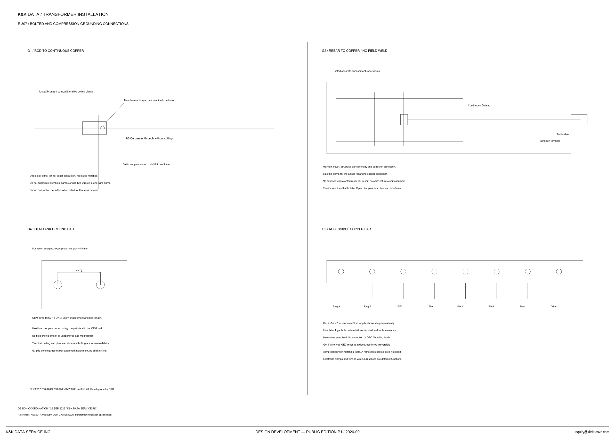
E-307 is the bolted and compression grounding connections sheet under the transformer-installation heading. It draws four details. G1 is the rod-to-continuous-copper clamp. G2 is the rebar-to-copper takeoff, and its title includes no field weld. G4 is the OEM tank ground pad. G5 is the accessible copper bar. Two further rules are printed as note lines, not as their own titled figures: G3, pile bonding, sits under the G4 notes, and G6, the wire-type GEC splice, sits under the G5 notes. The reference line cites NEC 2017 Article 250, OEM GA 08 Sep 2026, and the transformer installation specification. Design coordination is 26 SEP 2026. The line under the details marks detail geometry NTS. On G4 the illustration is enlarged 20x and the physical hole pitch is 44.5 mm. On G5 the bar is marked shown diagrammatically.
Rod clamp and rebar takeoff
G1 is a listed bronze / compatible-alloy bolted clamp. The callout says manufacturer torque and one permitted conductor. The 2/0 Cu passes through without cutting. The rod on the same detail is a 3/4 in copper-bonded rod, and the length printed with it is a 10 ft candidate. The notes require a direct-soil-burial listing, with the exact conductor and rod sizes matched. They say not to substitute plumbing clamps, and not to use two wires in a one-wire clamp. A buried connection is permitted when the fitting is listed for that environment: the sentence is a permission tied to the listing, and the sheet does not name a selected clamp. G2 is the other joint. It draws a listed concrete-encasement rebar clamp, a continuous copper lead, and an accessible transition terminal at the end of that lead. Cover, structural bar continuity and corrosion protection are to be maintained. The clamp is to be sized for the actual rebar and the actual copper conductor, and those sizes are not printed here. No exposed unprotected rebar tail in soil, and no earth-return credit is assumed. The count the sheet does give is one identifiable takeoff per pier, plus four pile-head interfaces. A careful reader keeps the two joints apart: at G1 the 2/0 passes through without cutting, and at G2 the lead ends at an accessible transition terminal, with no field weld and with no earth-return credit assumed.
Tank pad, pile bond, and the copper bar
G4 draws the OEM tank ground pad. The illustration is enlarged 20x, and the physical hole pitch is 44.5 mm, dimensioned across the two holes in that view. The threads are 1/2-13 UNC, and the same line says to verify engagement and bolt length, so that check remains an instruction on the sheet. Use a listed copper-conductor lug compatible with the OEM pad. No field drilling of the tank or unapproved pad modification. Terminal bolting and pile-head structural bolting are separate details. G3 is the next line in that block: use a maker-approved attachment for pile bonding, with no shaft drilling. That attachment is stated in the note and is not given its own figure. G5 is the accessible copper bar. Left to right, the positions are Ring A, Ring B, GEC, Site, Pier1, Pier2, Tank and Other. The bar is at least 1/4 x 2 in, the length is a proposed 24 in, and the view is shown diagrammatically. Use listed lugs. The hole pattern follows the terminal and the tool clearances. No routine energized disconnection of the GEC / bonding leads. G6 is conditional: if a wire-type GEC must be spliced, use listed irreversible compression with matching tools. A removable bolt splice is not used. The closing line keeps the jobs apart, and it is worth reading exactly: electrode clamps and wire-to-wire GEC splices are different functions.
Status
Published at Design Development — Public Edition P1 (title block: 2026-09; design coordination: 26 SEP 2026). This is a reference design for study and evaluation. The open items are written on the details themselves. The rod length is a 10 ft candidate. G1 says manufacturer torque and does not print a torque value. G2 says to size the clamp for the actual rebar and copper conductor, does not print those sizes, and assumes no earth-return credit. G4 says to verify engagement and bolt length. The copper-bar length is a proposed 24 in, the bar is shown diagrammatically, and detail geometry is NTS. The 44.5 mm figure is the physical hole pitch on the view enlarged 20x. G3 says to use a maker-approved attachment for pile bonding and does not draw that attachment. Beside the details, the sheet cites NEC 2017 250.64(C), 250.64(F)(3), 250.68 and 250.70.
Sheet guide — the devices on this drawing
G1 — rod to continuous copper
G1 is a listed bronze / compatible-alloy bolted clamp on the continuous copper. The 2/0 Cu passes through without cutting, and the callout says manufacturer torque and one permitted conductor. The rod is a 3/4 in copper-bonded rod, with the length marked as a 10 ft candidate.
G1 notes — burial listing and one conductor
The lines under the clamp require a direct-soil-burial listing, with the exact conductor and rod sizes matched. They say not to substitute plumbing clamps, and not to use two wires in a one-wire clamp. A buried connection is permitted when the fitting is listed for that environment.
G2 — rebar to copper, no field weld
G2 draws a listed concrete-encasement rebar clamp, a continuous copper lead, and an accessible transition terminal at the end of that lead. The detail is titled rebar to copper / no field weld. Cover, structural bar continuity and corrosion protection are to be maintained.
G2 notes — takeoff per pier and pile heads
The clamp is to be sized for the actual rebar and the actual copper conductor. No exposed unprotected rebar tail in soil, and no earth-return credit is assumed. It calls for one identifiable takeoff per pier, plus four pile-head interfaces.
G4 — OEM tank ground pad
The G4 illustration is enlarged 20x, and it gives the physical hole pitch as 44.5 mm across the two holes in the view. Threads are 1/2-13 UNC. The same line says to verify engagement and bolt length.
G3 — pile bonding, under the G4 limits
Under the pad, the sheet calls for a listed copper-conductor lug compatible with the OEM pad, and it states no field drilling of the tank or unapproved pad modification. Terminal bolting and pile-head structural bolting are separate details. G3 says to use a maker-approved attachment for pile bonding, with no shaft drilling.
G5 — accessible copper bar
G5 is the accessible copper bar, shown diagrammatically. The positions, left to right, are Ring A, Ring B, GEC, Site, Pier1, Pier2, Tank and Other. The bar is at least 1/4 x 2 in, and the length is a proposed 24 in.
G6 — wire-type GEC splice
Listed lugs are called for, and the hole pattern follows the terminal and the tool clearances. No routine energized disconnection of the GEC / bonding leads. If a wire-type GEC must be spliced, G6 calls for listed irreversible compression with matching tools, and a removable bolt splice is not used; electrode clamps and wire-to-wire GEC splices are different functions.
NEC line — 250.64, 250.68, 250.70, and NTS
The line above the title block cites NEC 2017 250.64(C), 250.64(F)(3), 250.68 and 250.70, and it marks detail geometry NTS. Design coordination is dated 26 SEP 2026. The title block reads Design Development — Public Edition P1 / 2026-09, with references to NEC 2017 Article 250, OEM GA 08 Sep 2026, and the transformer installation specification.
Get the full drawing set
This sheet is one page of the Electrical Drawing Book — Public Edition P1 (88 pages, 14 MB) — a direct PDF download with a published SHA-256 checksum, no registration. The complete coordinated set is on the downloads page. Background guides: data center one-line diagrams · GB300 NVL72 facility requirements · liquid cooling and CDU design.
Questions about any device or parameter on this sheet: inquiry@kkdatasvc.com or the contact page.