
Data Center Lab · Reference Designs · Electrical
Sheet E-306: The 6000 x 6000 Earth Grid Is a Candidate, and the Conductors Stay Separate
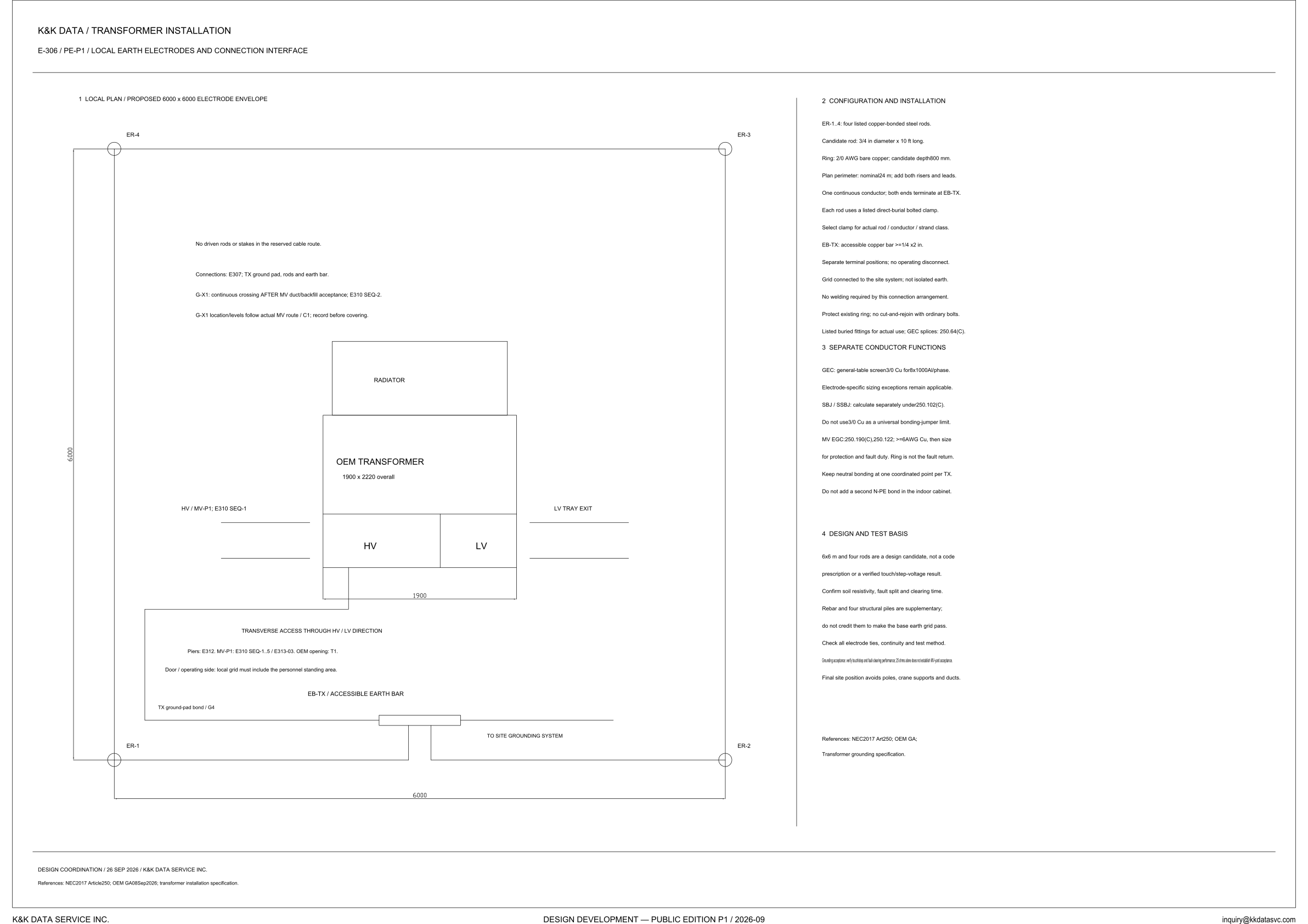
A proposed 6000 x 6000 electrode envelope — note 4 calls the 6x6 m layout with four rods a design candidate — with a 2/0 AWG bare-copper ring, while the notes keep that ring, the GEC screen, the SBJ / SSBJ and the MV EGC as separate conductors.
Design Development — Public Edition P1: a reference design for study and evaluation, not a construction issue, not sealed by an Engineer of Record.
Scroll or pinch to zoom, drag to pan, click a highlighted device for its explanation. Vector drawing — it stays sharp at any magnification.
← E-303 · All electrical sheets · E-307 →
What this sheet shows
E-306 is the local plan of the earth electrodes at one OEM transformer. The coordination line on the sheet is 26 SEP 2026. The view is titled a proposed 6000 x 6000 electrode envelope, and note 4 names the candidate for this grid as 6 x 6 m with four rods. ER-1, ER-2, ER-3 and ER-4 sit at the four corners. The OEM transformer is drawn inside the envelope at 1900 x 2220 overall, with the radiator on one face of the tank and the HV and LV compartments on the other. One side is labeled HV / MV-P1; E310 SEQ-1, and the other side is the LV tray exit. On the door and operating side the plan notes transverse access through the HV / LV direction, and it refers the piers to E312, MV-P1 to E310 SEQ-1..5 / E313-03, and the OEM opening to T1. EB-TX, the accessible earth bar, is on that side; the tank bond is marked TX ground-pad bond / G4, and the line continues to the site grounding system. The open area of the envelope states that no driven rods or stakes go in the reserved cable route, and it refers the ground pad, the rods and the earth bar to E307. The reference line cites NEC 2017 Article 250, OEM GA 08 Sep 2026, and the transformer installation specification.
Rods, ring, and the accessible bar
Note 2 is headed configuration and installation. ER-1..4 are four listed copper-bonded steel rods, and the size line calls the rod a candidate: 3/4 in diameter by 10 ft long. Each rod uses a listed direct-burial bolted clamp, and the clamp is selected for the actual rod, conductor and strand class. The ring is 2/0 AWG bare copper, with a candidate depth of 800 mm. The plan perimeter is a nominal 24 m, and that line says to add both risers and leads. One continuous conductor is required, and both ends terminate at EB-TX, which keeps the ring landed on the accessible bar. That bar is an accessible copper bar of at least 1/4 x 2 in, with separate terminal positions and no operating disconnect. The grid is connected to the site system and is not isolated earth; the plan shows the same continuation to the site grounding system. No welding is required by this connection arrangement. The note says to protect an existing ring and not to cut-and-rejoin it with ordinary bolts, to use listed buried fittings for the actual use, and to make GEC splices under 250.64(C).
Separate conductor functions
Note 3 keeps the conductor functions from sharing one size. The GEC entry is a general-table screen, 3/0 Cu for 8 x 1000 Al per phase, and electrode-specific sizing exceptions remain applicable. SBJ / SSBJ are to be calculated separately under 250.102(C). The note says not to use 3/0 Cu as a universal bonding-jumper limit, so the screen is not a number that can be copied onto the jumpers. The MV EGC is sized from 250.190(C) and 250.122: at least 6 AWG Cu, then sized for the protection and the fault duty. That sentence says the ring is not the fault return. Neutral bonding stays at one coordinated point per TX, and a second N-PE bond is not to be added in the indoor cabinet. The heading keeps the 2/0 AWG bare copper ring, the 3/0 Cu GEC screen, the SBJ / SSBJ and the MV EGC as separate conductor functions.
Status
Published at Design Development — Public Edition P1 (title block: 2026-09; design coordination: 26 SEP 2026). This is a reference design for study and evaluation, and note 4 prints the limits on the grid in the same column as the candidate. The 6 x 6 m envelope and the four rods are a design candidate, not a code prescription and not a verified touch/step-voltage result. The note says to confirm soil resistivity, fault split and clearing time. Rebar and the four structural piles are supplementary, and they are not to be credited to make the base earth grid pass. The note says to check all electrode ties, continuity and the test method. Grounding acceptance is stated as a verification of touch/step and fault-clearing performance, and 25 ohms alone does not establish MV-yard acceptance. The final site position avoids poles, crane supports and ducts. G-X1, on the plan, is a continuous crossing after MV duct and backfill acceptance, at E310 SEQ-2; its location and levels follow the actual MV route / C1 and are to be recorded before covering.
Sheet guide — the devices on this drawing
ER-4 and ER-3 — rods opposite the earth bar
ER-4 and ER-3 are the two corner rods on the side of the 6000 x 6000 ring opposite the earth bar. Note 2 groups all four, ER-1..4, as listed copper-bonded steel rods, and the rod it names is a candidate, 3/4 in diameter by 10 ft long. Each rod uses a listed direct-burial bolted clamp, selected for the actual rod, conductor and strand class.
ER-1 and ER-2 — rods on the earth-bar side
ER-1 and ER-2 close the other two corners of the ring. The 6000 dimension along this side is the plan width of the proposed envelope. The door and operating-side note, EB-TX and the continuation to the site grounding system are drawn along this side of the envelope.
OEM transformer — 1900 x 2220 overall
The tank is labeled OEM transformer, 1900 x 2220 overall. The radiator is drawn on one face, and the HV and LV compartments are on the opposite face. One side is labeled HV / MV-P1; E310 SEQ-1, and the other side is marked LV tray exit.
G-X1 — crossing after MV duct acceptance
These notes sit in the open part of the envelope. No driven rods or stakes go in the reserved cable route, and the TX ground pad, the rods and the earth bar are referred to E307 for the connections. G-X1 is a continuous crossing after MV duct and backfill acceptance, at E310 SEQ-2, and its location and levels follow the actual MV route, C1, to be recorded before covering.
EB-TX — accessible earth bar
EB-TX is the accessible earth bar on the door and operating side, where the local grid must include the personnel standing area. The plan marks TX ground-pad bond / G4 on this side and continues the bar to the site grounding system. The same block notes transverse access through the HV / LV direction, and it points the piers to E312, MV-P1 to E310 SEQ-1..5 / E313-03, and the OEM opening to T1.
Note 2 — candidate rod, 2/0 ring, and EB-TX
Note 2 names a candidate rod of 3/4 in by 10 ft, a 2/0 AWG bare copper ring at a candidate depth of 800 mm, and a nominal plan perimeter of 24 m with both risers and leads added. One continuous conductor has both ends at EB-TX. The bar is at least 1/4 x 2 in, with separate terminals and no operating disconnect; the grid connects to the site system and is not isolated earth. No welding is required by this arrangement, an existing ring is not to be cut and rejoined with ordinary bolts, and GEC splices are under 250.64(C).
Note 3 — GEC screen, SBJ / SSBJ, and MV EGC
The GEC is a general-table screen of 3/0 Cu for 8 x 1000 Al per phase, and electrode-specific sizing exceptions remain applicable. SBJ / SSBJ are to be calculated separately under 250.102(C), and 3/0 Cu is not a universal bonding-jumper limit. The MV EGC follows 250.190(C) and 250.122, at least 6 AWG Cu and then sized for protection and fault duty, and the note says the ring is not the fault return. Neutral bonding stays at one coordinated point per TX, with no second N-PE bond in the indoor cabinet.
Note 4 — candidate grid, not a 25-ohm acceptance
Note 4 says the 6 x 6 m grid and the four rods are a design candidate, not a code prescription and not a verified touch/step-voltage result. Soil resistivity, fault split and clearing time are to be confirmed, and rebar plus the four structural piles are not to be credited toward making the base earth grid pass. Ties, continuity and the test method are to be checked. The acceptance line says to verify touch/step and fault-clearing performance, and that 25 ohms alone does not establish MV-yard acceptance. The final site position avoids poles, crane supports and ducts.
Get the full drawing set
This sheet is one page of the Electrical Drawing Book — Public Edition P1 (88 pages, 14 MB) — a direct PDF download with a published SHA-256 checksum, no registration. The complete coordinated set is on the downloads page. Background guides: data center one-line diagrams · GB300 NVL72 facility requirements · liquid cooling and CDU design.
Questions about any device or parameter on this sheet: inquiry@kkdatasvc.com or the contact page.