
Data Center Lab · Reference Designs · Electrical
Sheet E-303: 60 in Cover to the Top of the Conduit, and a Wheel-Load Screen Still Open to Compare
The 60 in cover is defined to the top of the conduit, and the axle pressures under the section are a screen to compare with the selected conduit and the ground limits.
Design Development — Public Edition P1: a reference design for study and evaluation, not a construction issue, not sealed by an Engineer of Record.
Scroll or pinch to zoom, drag to pan, click a highlighted device for its explanation. Vector drawing — it stays sharp at any magnification.
← E-302 · All electrical sheets · E-306 →
What this sheet shows
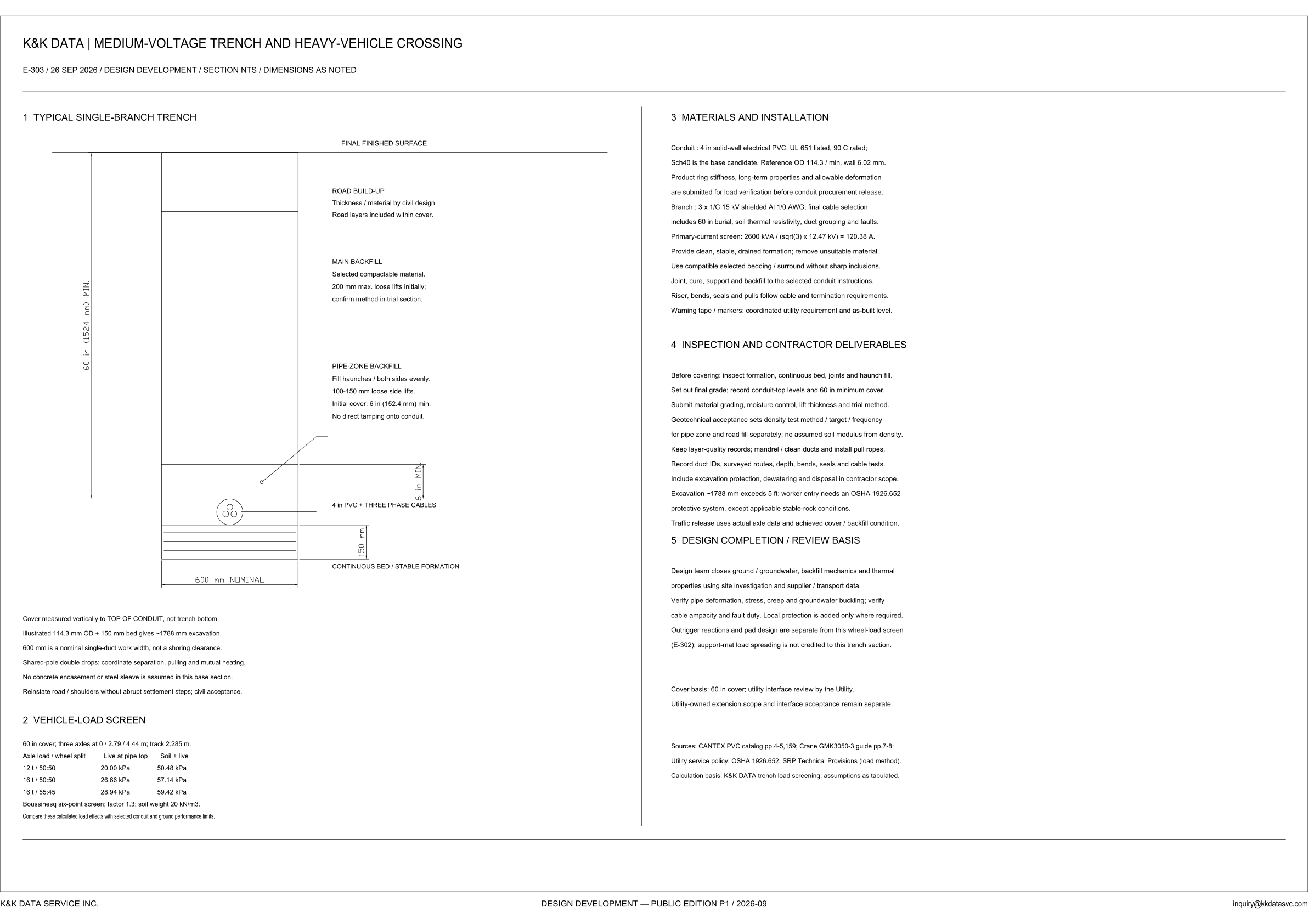
E-303 is the section for the medium-voltage trench and the heavy-vehicle crossing. The header marks the view SECTION NTS, not to scale, with dimensions as noted, and dates the sheet 26 SEP 2026. The drawn section is a typical single branch. From the final finished surface downward it calls out road build-up, main backfill, pipe-zone backfill, a 4 in PVC duct with three-phase cables, and a continuous bed on stable formation. Under that section the sheet runs a vehicle-load screen. The right-hand column is the written basis: materials and installation, inspection and contractor deliverables, and design completion. The footer places the sheet in Design Development — Public Edition P1 / 2026-09.
How the cover and the layers are defined
The note under the section defines cover vertically to the top of the conduit, not to the trench bottom. Road-build-up thickness and material are by civil design, and the same callout says the road layers are included within the cover. The vehicle-load screen and the design-completion note both state the cover basis as 60 in, and the inspection note calls for conduit-top levels and a 60 in minimum cover to be recorded. Main backfill is selected compactable material, in 200 mm maximum loose lifts initially, and the note says to confirm the method in a trial section. Pipe-zone backfill fills the haunches on both sides evenly, in 100-150 mm loose side lifts, with an initial cover of 6 in (152.4 mm) minimum and no direct tamping onto the conduit. The illustration note then states the excavation that belongs to that picture: an illustrated 114.3 mm OD plus a 150 mm bed gives ~1788 mm of excavation. The 600 mm dimension is labeled nominal, and the note says it is a single-duct work width, not a shoring clearance. This base section assumes no concrete encasement and no steel sleeve. Shared-pole double drops are named only as a coordination item: separation, pulling and mutual heating. Road and shoulders are reinstated without abrupt settlement steps, with civil acceptance.
Two screens, and what they do not close
The vehicle-load block is a screen of calculated effects. Its geometry line reads 60 in cover, three axles at 0 / 2.79 / 4.44 m, and a track of 2.285 m. Three rows give live pressure at the pipe top and the soil-plus-live total. A 12 t axle at a 50:50 wheel split is 20.00 kPa live and 50.48 kPa soil plus live. A 16 t axle at 50:50 is 26.66 kPa and 57.14 kPa. A 16 t axle at 55:45 is 28.94 kPa and 59.42 kPa. The method line is a Boussinesq six-point screen, factor 1.3, soil weight 20 kN/m3. The last line says to compare these calculated load effects with the selected conduit and the ground performance limits. No conduit limit and no pass/fail are printed beside the table. The materials note runs a second screen, for primary current: 2600 kVA / (sqrt(3) × 12.47 kV) = 120.38 A. The branch is written as 3 × 1/C 15 kV shielded Al, 1/0 AWG, and that same sentence says final cable selection includes the 60 in burial, soil thermal resistivity, duct grouping and faults. The line is titled a primary-current screen. Design completion names cable ampacity and fault duty separately, as checks still to verify.
Status
Published at Design Development — Public Edition P1 (title block: 2026-09; sheet line: 26 SEP 2026): a reference design for study and evaluation, with the open items written on the sheet. The conduit line specifies 4 in solid-wall electrical PVC, UL 651 listed and 90 C rated, and states that Sch40 is the base candidate, with a reference OD of 114.3 mm and a minimum wall of 6.02 mm. Product ring stiffness, long-term properties and allowable deformation are submitted for load verification before conduit procurement release. Geotechnical acceptance sets the density test method, target and frequency for the pipe zone and the road fill separately; the note states that no soil modulus is assumed from density. Before covering, the note calls for inspection of formation, the continuous bed, joints and haunch fill, and for the 60 in minimum cover to be recorded at the conduit top. The excavation note states that ~1788 mm exceeds 5 ft, so worker entry needs an OSHA 1926.652 protective system, except applicable stable-rock conditions, and traffic release uses actual axle data and the achieved cover and backfill condition. Design completion assigns ground, groundwater, backfill mechanics and thermal properties to site investigation and to supplier and transport data, and it calls for verification of pipe deformation, stress, creep and groundwater buckling, and of cable ampacity and fault duty. Local protection is added only where required. Outrigger reactions and pad design are separate from this wheel-load screen and are referred to E-302; support-mat load spreading is not credited to this trench section. The cover basis remains 60 in, with utility interface review by the Utility, and utility-owned extension scope and interface acceptance remain separate. Sources named on the sheet are the CANTEX PVC catalog, pp.4-5,159; the Crane GMK3050-3 guide, pp.7-8; the utility service policy; OSHA 1926.652; and SRP Technical Provisions for the load method.
Sheet guide — the devices on this drawing
60 in cover — to the top of the conduit
The vertical dimension on the typical single-branch section is the cover over the duct. The note defines that cover vertically to the top of the conduit, not to the trench bottom, and the inspection note calls it a 60 in minimum to be recorded at the conduit top. Road layers are included within that cover; their thickness and material are by civil design.
Backfill layers — road, main fill, pipe zone
Main backfill is selected compactable material, in 200 mm maximum loose lifts initially, and the note says to confirm the method in a trial section. Pipe-zone backfill fills the haunches on both sides evenly, in 100-150 mm loose side lifts, and the initial cover over the conduit is 6 in (152.4 mm) minimum. The pipe-zone note bars direct tamping onto the conduit.
4 in PVC — three-phase cables on a 150 mm bed
The duct callout is 4 in PVC with three-phase cables, set on a continuous bed over stable formation. The bed dimension on the section is 150 mm, and the width under the trench is labeled 600 mm nominal. The note under the drawing says that 600 mm is a single-duct work width, not a shoring clearance.
Section notes — ~1788 mm, width, no encasement assumed
The illustration note states that a 114.3 mm OD plus the 150 mm bed gives ~1788 mm of excavation, with cover taken to the top of the conduit. This base section assumes no concrete encasement and no steel sleeve. Shared-pole double drops are a coordination item for separation, pulling and mutual heating, and the road and shoulders are reinstated without abrupt settlement steps, with civil acceptance.
Vehicle-load screen — 12 t and 16 t at the pipe top
The screen uses 60 in cover, three axles at 0 / 2.79 / 4.44 m, and a track of 2.285 m. A 12 t axle at 50:50 is 20.00 kPa live and 50.48 kPa soil plus live; 16 t at 50:50 is 26.66 kPa and 57.14 kPa; 16 t at 55:45 is 28.94 kPa and 59.42 kPa. It is a Boussinesq six-point screen, factor 1.3, soil weight 20 kN/m3, and the note says to compare those effects with the selected conduit and the ground performance limits.
Materials — Sch40 candidate and a 120.38 A screen
The conduit is 4 in solid-wall electrical PVC, UL 651 listed, 90 C rated, and Sch40 is named as the base candidate, with reference OD 114.3 mm and minimum wall 6.02 mm. Ring stiffness, long-term properties and allowable deformation are submitted for load verification before conduit procurement release. The branch is 3 × 1/C 15 kV shielded Al, 1/0 AWG, the primary-current screen is 2600 kVA / (sqrt(3) × 12.47 kV) = 120.38 A, and final cable selection includes the 60 in burial, soil thermal resistivity, duct grouping and faults.
Inspection — 60 in record and OSHA 1926.652
Before covering, the note calls for inspection of formation, the continuous bed, joints and haunch fill, and for conduit-top levels and the 60 in minimum cover to be recorded. Geotechnical acceptance sets density method, target and frequency for the pipe zone and the road fill separately, and no soil modulus is assumed from density. Excavation of ~1788 mm exceeds 5 ft, so worker entry needs an OSHA 1926.652 protective system, except applicable stable-rock conditions, and traffic release uses actual axle data and the achieved cover and backfill condition.
Design completion — open checks; outriggers on E-302
The design-completion note has the design team close ground, groundwater, backfill mechanics and thermal properties using site investigation and supplier and transport data, and it calls for verification of pipe deformation, stress, creep, groundwater buckling, cable ampacity and fault duty. Local protection is added only where required. Outrigger reactions and pad design are separate from this wheel-load screen and are referred to E-302, and support-mat load spreading is not credited to this trench section.
Cover basis and sources — utility scope remains separate
The cover basis on the sheet is 60 in, with utility interface review by the Utility. Utility-owned extension scope and interface acceptance remain separate. The source line names the CANTEX PVC catalog, pp.4-5,159; the Crane GMK3050-3 guide, pp.7-8; the utility service policy; OSHA 1926.652; and SRP Technical Provisions for the load method, and the calculation basis is the K&K DATA trench load screening, assumptions as tabulated.
Get the full drawing set
This sheet is one page of the Electrical Drawing Book — Public Edition P1 (88 pages, 14 MB) — a direct PDF download with a published SHA-256 checksum, no registration. The complete coordinated set is on the downloads page. Background guides: data center one-line diagrams · GB300 NVL72 facility requirements · liquid cooling and CDU design.
Questions about any device or parameter on this sheet: inquiry@kkdatasvc.com or the contact page.