
Data Center Lab · Reference Designs · Electrical
Sheet E-302: Crane Access on a 6.5 m Shared Road over the Buried MV Crossing
The slew axis here is an example, the tail is an OEM reference that still needs a slew check, and isolating a branch leaves the overhead trunk energized.
Design Development — Public Edition P1: a reference design for study and evaluation, not a construction issue, not sealed by an Engineer of Record.
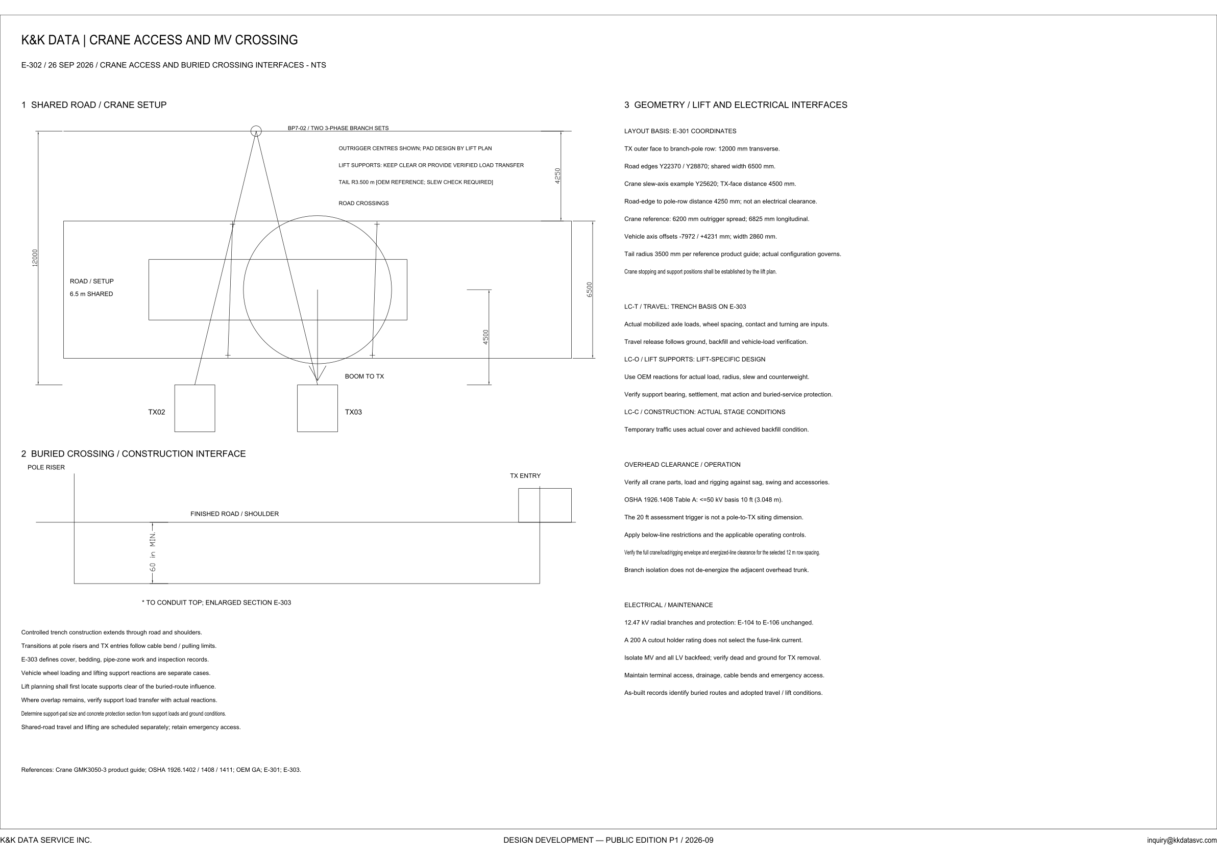
Scroll or pinch to zoom, drag to pan, click a highlighted device for its explanation. Vector drawing — it stays sharp at any magnification.
← E-301 · All electrical sheets · E-303 →
What this sheet shows
E-302 is marked NTS, not to scale, and dated 26 SEP 2026. It is the interface between crane access and the buried crossing, not a lift plan and not the trench section. The plan puts branch pole BP7-02 on the pole row, labeled two 3-phase branch sets, beside a road band marked road / setup and 6.5 m shared. Road crossings is the last line of the note stack above the band, with the outrigger, lift-support, and tail lines. Outrigger centres are shown, and the same note gives pad design to the lift plan. Lift supports are to be kept clear or given a verified load transfer. The tail is labeled R3.500 m, in a bracket that reads OEM reference, slew check required. On the transformer side of the road the plan draws TX02 and TX03, and the boom leader reads boom to TX at TX03. Under that plan the crossing section runs from the pole riser, under the finished road and shoulder, to the TX entry. The depth mark on that section is starred to the conduit top, the enlarged section is E-303, and the figure printed there is a 60 in minimum.
Coordinates, and the figures that are not clearances
The geometry block takes its layout basis from E-301 coordinates. TX outer face to the branch-pole row is 12000 mm transverse, and the overhead note calls the selected row spacing 12 m when it asks for the full crane, load and rigging envelope to be checked at that spacing. Road edges are Y22370 and Y28870, and the shared width is 6500 mm, the same 6.5 m written in the road. The crane slew-axis example is Y25620, with a TX-face distance of 4500 mm. Those three coordinates can be checked against each other: Y25620 lies halfway between the road edges printed on the same lines. The road-edge to pole-row distance is 4250 mm, and that line says the 4250 mm is not an electrical clearance. The crane-reference lines then print an outrigger spread of 6200 mm, a longitudinal figure of 6825 mm, vehicle axis offsets of -7972 / +4231 mm, and a width of 2860 mm. Only the tail line names a source: 3500 mm per the reference product guide, and the actual configuration governs. The sheet's reference list names the GMK3050-3 product guide, and the R3.500 m on the plan is that tail written in metres. Stopping and support positions shall be established by the lift plan.
Three load cases this sheet does not close
The crossing notes keep the two duties on this road apart. Vehicle wheel loading and lifting-support reactions are separate cases. Lift planning shall first locate supports clear of the buried-route influence. Where overlap remains, support load transfer is verified with the actual reactions. Support-pad size and the concrete protection section are determined from the support loads and the ground conditions; neither size is given here. Three cases are named. LC-T, travel, takes its trench basis on E-303. Actual mobilized axle loads, wheel spacing, contact and turning are inputs, and travel release follows ground, backfill and vehicle-load verification. LC-O, lift supports, is lift-specific: use OEM reactions for the actual load, radius, slew and counterweight, then verify support bearing, settlement, mat action and buried-service protection. LC-C, construction, uses the stage as it stands: temporary traffic uses the actual cover and the achieved backfill condition. Around those cases the notes require controlled trench construction through the road and the shoulders, and transitions at the pole risers and the TX entries that follow cable bend and pulling limits. Shared-road travel and lifting are scheduled separately, and emergency access is retained. Cover, bedding, pipe-zone work and inspection records are defined on E-303.
The live trunk, and what stays open
The overhead block is a check the lift still has to perform. It says to verify all crane parts, the load and the rigging against sag, swing and accessories. OSHA 1926.1408 Table A is cited as a <=50 kV basis of 10 ft (3.048 m). The 20 ft assessment trigger is not a pole-to-TX siting dimension. Below-line restrictions and the applicable operating controls apply, and the full crane, load and rigging envelope is to be verified against energized-line clearance for the selected 12 m row spacing. Branch isolation does not de-energize the adjacent overhead trunk, so the energized-line check is still against that trunk. That boundary is the subject of the electrical architecture notes. The electrical design itself is unchanged: 12.47 kV radial branches and protection stay as drawn on E-104 to E-106. A 200 A cutout holder rating does not select the fuse-link current. Transformer removal is isolate the MV and all LV backfeed, then verify dead and ground, while terminal access, drainage, cable bends and emergency access are maintained. Records of the work are to identify the buried routes and the travel and lift conditions that were adopted. Published at Design Development — Public Edition P1 (sheet line 26 SEP 2026; title block 2026-09): a reference design for study and evaluation. Pad design is by the lift plan, and stopping and support positions shall be established by the lift plan. The tail bracket is OEM reference; slew check required, and the geometry line says the 3500 mm tail is per the reference product guide and that the actual configuration governs. OEM reactions and the mobilized axle inputs are not printed here. The reference line also names OSHA 1926.1402 and 1926.1411, the OEM general arrangement, E-301 and E-303.
Sheet guide — the devices on this drawing
BP7-02 — two 3-phase branch sets
BP7-02 is the branch pole on the pole row in this view, labeled two 3-phase branch sets. The geometry block gives that row as 12000 mm transverse from the transformer outer face, and the overhead note uses the same 12 m spacing for the crane-envelope check. Isolating a branch here does not de-energize the adjacent overhead trunk.
Outrigger centres — pads and tail left open
The plan says the outrigger centres are shown and that pad design is by the lift plan. Lift supports are to be kept clear or given a verified load transfer. The tail callout reads R3.500 m, limited by the bracket to an OEM reference with a slew check required. The geometry block repeats that tail as 3500 mm per the reference product guide, with the actual configuration governing.
Shared road — 6.5 m and the example axis
The road band is labeled road / setup and 6.5 m shared. Road crossings sits above the rectangle, the last line of the note stack with the outrigger, lift-support, and tail lines. The geometry block gives the same width as 6500 mm between road edges Y22370 and Y28870. The crane slew-axis example is Y25620, printed with a TX-face distance of 4500 mm. The block says stopping and support positions shall be established by the lift plan.
TX03 — boom to TX, with TX02 beside it
TX02 and TX03 are the transformer positions drawn on the transformer side of the road. The boom leader is marked boom to TX and is drawn to TX03. The 4500 mm figure beside this reach is the example slew-axis to TX-face distance in the geometry block. Removal of a transformer follows the electrical note: isolate MV and all LV backfeed, then verify dead and ground.
Buried crossing — pole riser to TX entry
This is the construction interface, not the enlarged trench. The section runs from the pole riser, under the finished road and shoulder, to the TX entry. The vertical figure reads 60 in minimum, and the star note says that dimension is to conduit top. Cover, bedding, pipe-zone work and the inspection records are on the enlarged section, E-303.
Crossing notes — wheel loads and lift supports
Controlled trench construction extends through the road and the shoulders. Transitions at the pole risers and the TX entries follow cable bend and pulling limits. Vehicle wheel loading and lifting-support reactions are separate cases. Lift planning first locates supports clear of the buried-route influence, and where overlap remains the load transfer is verified with actual reactions. Shared-road travel and lifting are scheduled separately, and emergency access is retained.
Layout basis — E-301 coordinates
The layout basis is the E-301 coordinates. TX outer face to the branch-pole row is 12000 mm transverse. Road edges are Y22370 and Y28870, shared width 6500 mm. Crane-reference figures are 6200 mm outrigger spread and 6825 mm longitudinal, with vehicle axis offsets -7972 / +4231 mm and a width of 2860 mm. The 4250 mm road-edge to pole-row distance is printed with a limit: it is not an electrical clearance.
LC-T, LC-O, LC-C — three cases still open
LC-T is travel, and its trench basis is E-303. Actual mobilized axle loads, wheel spacing, contact and turning are inputs, and travel release follows ground, backfill and vehicle-load verification. LC-O is the lift supports: OEM reactions for the actual load, radius, slew and counterweight, then bearing, settlement, mat action and buried-service protection. LC-C is construction: temporary traffic uses the actual cover and the achieved backfill condition.
Overhead clearance — Table A and the live trunk
Verify all crane parts, the load and the rigging against sag, swing and accessories. OSHA 1926.1408 Table A is cited as an at-or-below 50 kV basis of 10 ft (3.048 m). The 20 ft assessment trigger is not a pole-to-TX siting dimension. Below-line restrictions and the applicable operating controls apply, and the full envelope is checked for the selected 12 m row spacing. Branch isolation does not de-energize the adjacent overhead trunk.
Electrical maintenance — 12.47 kV left unchanged
12.47 kV radial branches and their protection are unchanged from E-104 to E-106. A 200 A cutout holder rating does not select the fuse-link current. For transformer removal, isolate MV and all LV backfeed, then verify dead and ground. Keep terminal access, drainage, cable bends and emergency access. Records of the work are to identify the buried routes and the travel and lift conditions that were adopted.
Get the full drawing set
This sheet is one page of the Electrical Drawing Book — Public Edition P1 (88 pages, 14 MB) — a direct PDF download with a published SHA-256 checksum, no registration. The complete coordinated set is on the downloads page. Background guides: data center one-line diagrams · GB300 NVL72 facility requirements · liquid cooling and CDU design.
Questions about any device or parameter on this sheet: inquiry@kkdatasvc.com or the contact page.