
Data Center Lab · Reference Designs · Electrical
Sheet E-301: Medium-Voltage Site Routing, Branch Poles and Shared Crane Access
How the 12.47 kV service physically reaches two GPU zones: branch poles, underground drops, no-tie point, and the one road that crane, generator extraction and daily traffic must share.
Design Development — Public Edition P1: a reference design for study and evaluation, not a construction issue, not sealed by an Engineer of Record.
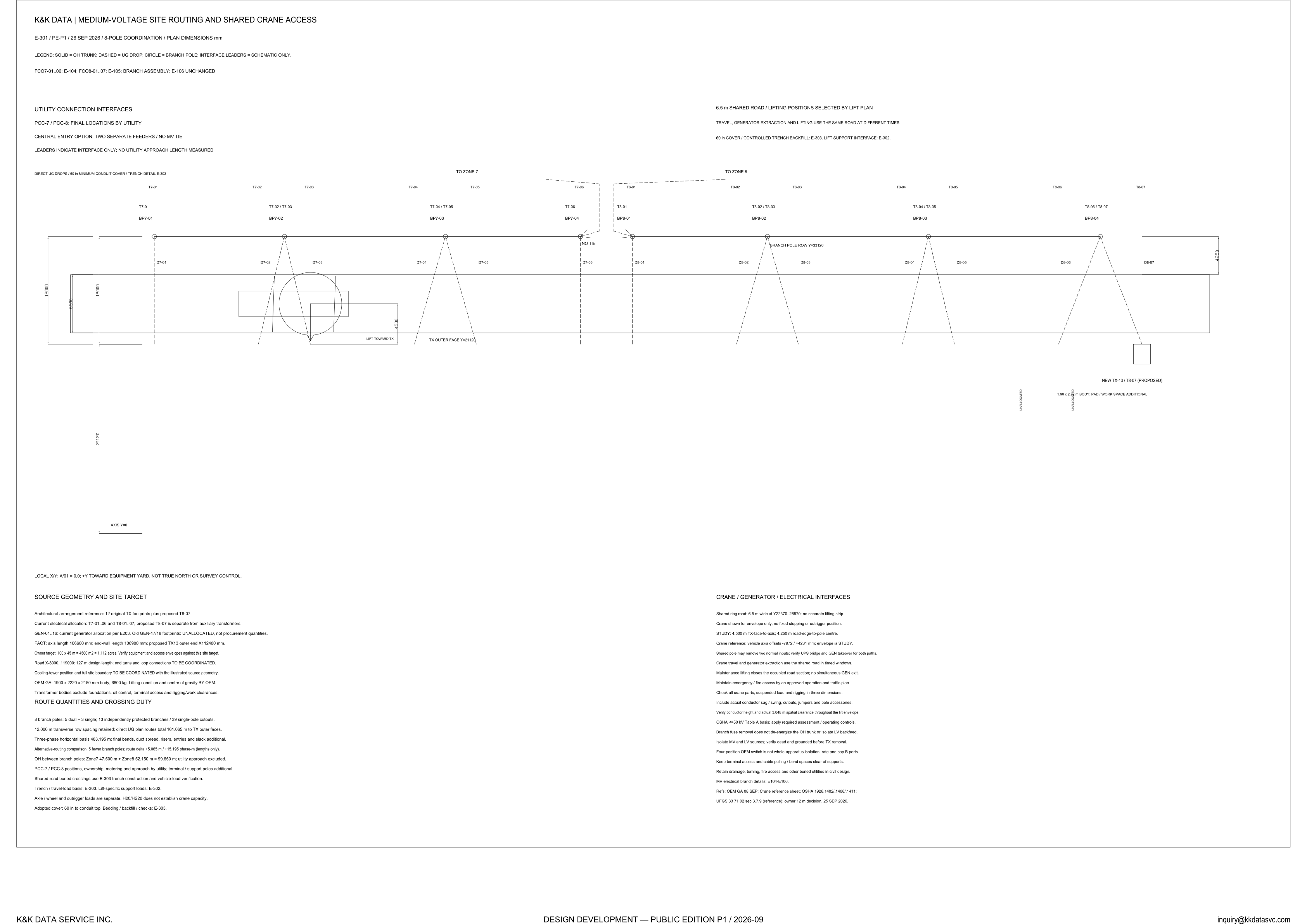
Scroll or pinch to zoom, drag to pan, click a highlighted device for its explanation. Vector drawing — it stays sharp at any magnification.
← E203 · All electrical sheets · E-302 →
What this sheet shows
E-301 is the plan view of the medium-voltage distribution: an overhead trunk along a branch-pole row feeding underground drops to Zone 7 (feeders T7-01…06) and Zone 8 (T8-01…07), with the two zone feeders deliberately kept separate — the sheet marks the NO TIE point between them. Utility connection interfaces (PCC-7 / PCC-8) are drawn as interfaces only, with final locations by the utility. A proposed additional transformer position (TX-13 / T8-07) is carried with its pad and work-space allowance.
Routing and crossing duty
The route-quantity notes give the engineering arithmetic: 8 branch poles (5 dual + 3 single), 13 independently protected branches on 39 single-pole cutouts, 12.000 m transverse row spacing, and direct underground plan routes totalling 161 m to the transformer outer faces, with three-phase horizontal basis at 483 m. Shared-road buried crossings carry 60-inch conduit cover with controlled trench backfill — trench construction and vehicle-load verification referenced to E-303.
The shared crane road
The second half of the sheet is construction-reality coordination: one 6.5 m shared ring road serves vehicle travel, generator extraction and crane lifting at different times, with lifting positions selected by lift plan. The notes walk the duty boundaries — crane envelope only, conductor sag and 3.048 m spatial clearance verification, OSHA ≤50 kV Table A basis, and the rule that maintenance lifting closes the occupied road section: no simultaneous generator exit. Civil interfaces (lift support, trench detail) are referenced to E-302/E-303.
Status
Design Development — Public Edition P1 (26 SEP 2026, 8-pole coordination revision). Utility approach lengths, PCC positions and final pole ownership are marked as utility-side open items on the sheet.
Sheet guide — the devices on this drawing
Zone 7 drops — T7-01…06
Six underground drops from the branch-pole row to the Zone 7 transformer positions — the same six feeders whose one-line chain is drawn on sheet E-107.
NO TIE — zones deliberately separate
Zone 7 and Zone 8 feeders come from the same substation but are kept with no medium-voltage tie: two separate feeders, central entry option. A failure-domain boundary drawn as two words on the plan.
Zone 8 drops — T8-01…07
Seven drops including the proposed T8-07 position. Branch assembly details are carried on E-105/E-106; feeder protection on 39 single-pole cutouts across 13 independently protected branches.
Proposed TX-13 / T8-07
A proposed new transformer position carried with its 1.90 x 2.22 m body, pad and additional work space — capacity growth drawn into the plan before it is committed.
Source geometry and route quantities
12 original transformer footprints plus the proposed T8-07; axis length 106.6 m; 8 branch poles, 13 protected branches, 161 m of direct UG routes; 60-inch adopted conduit cover. The quantity basis a GC can take off.
Crane / generator / electrical interface rules
One 6.5 m shared road for travel, generator extraction and lifting in timed windows; crane envelope STUDY at 4.5 m TX-face-to-axis; conductor clearance 3.048 m verified; OSHA ≤50 kV Table A basis; maintenance lifting closes the road section — no simultaneous generator exit.
Get the full drawing set
This sheet is one page of the Electrical Drawing Book — Public Edition P1 (88 pages, 14 MB) — a direct PDF download with a published SHA-256 checksum, no registration. The complete coordinated set is on the downloads page. Background guides: data center one-line diagrams · GB300 NVL72 facility requirements · liquid cooling and CDU design.
Questions about any device or parameter on this sheet: inquiry@kkdatasvc.com or the contact page.