
Data Center Lab · Reference Designs · Electrical
Sheet E203: Four Sections, Three Sync-Check Couplers, and 13 UPS Feeders
Four section buses and three sync-check couplers decide how much of the 16 x 1 MW study basis stays connected to the 13 UPS feeders when a section is isolated.
Design Development — Public Edition P1: a reference design for study and evaluation, not a construction issue, not sealed by an Engineer of Record.
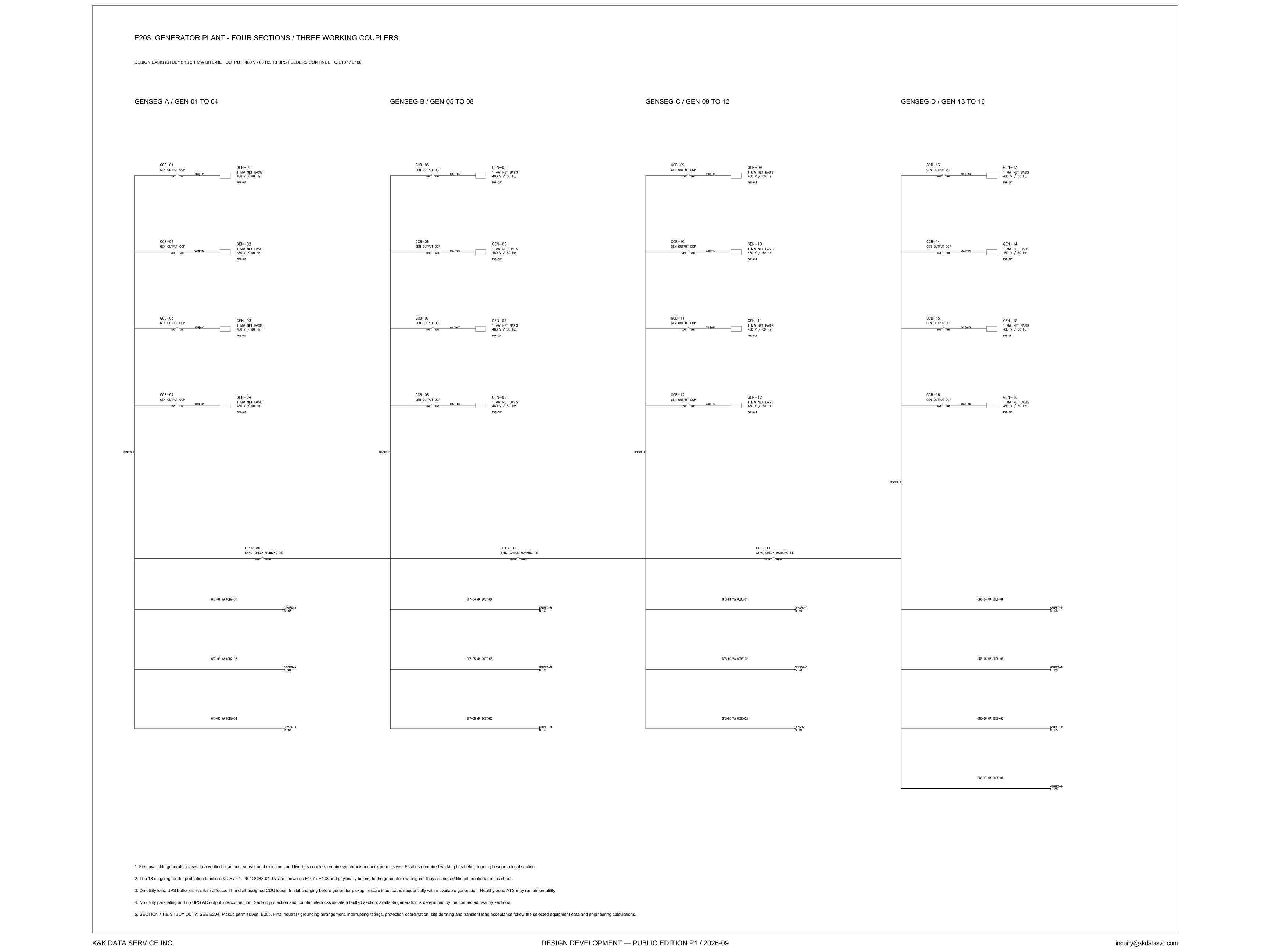
Scroll or pinch to zoom, drag to pan, click a highlighted device for its explanation. Vector drawing — it stays sharp at any magnification.
← E202 · All electrical sheets · E-301 →
What this sheet shows
E203 is the generator-plant one-line. The title reads four sections and three working couplers. The line under the title is labeled a design basis and a study: 16 x 1 MW site-net output, 480 V / 60 Hz, with 13 UPS feeders continuing to E107 / E108. Four headers divide the machines. GENSEG-A is GEN-01 to GEN-04. GENSEG-B is GEN-05 to GEN-08. GENSEG-C is GEN-09 to GEN-12. GENSEG-D is GEN-13 to GEN-16. Each block is marked 1 MW net basis at 480 V / 60 Hz. The breaker on the tap from that block to the section bus carries the machine number, GCB-01 through GCB-16, and the words GEN OUTPUT OCP. The bus is the vertical line at the left of the group, and it runs from the machines down through the tie and the outgoing lines. Three couplers join those buses. CPLR-AB runs from the GENSEG-A bus toward GENSEG-B. CPLR-BC runs from GENSEG-B toward GENSEG-C. CPLR-CD runs from GENSEG-C toward GENSEG-D. Each is labeled SYNC-CHECK WORKING TIE. Under the couplers the outgoing lines leave the bus and stop inside the section. They do not continue onto the next section bus. GENSEG-A has GF7-01 via GCB7-01, GF7-02 via GCB7-02, and GF7-03 via GCB7-03. GENSEG-B has GF7-04 via GCB7-04, GF7-05 via GCB7-05, and GF7-06 via GCB7-06. GENSEG-C has GF8-01 via GCB8-01, GF8-02 via GCB8-02, and GF8-03 via GCB8-03. GENSEG-D has four lines: GF8-04 via GCB8-04, GF8-05 via GCB8-05, GF8-06 via GCB8-06, and GF8-07 via GCB8-07.
Design intent you can read off the sheet
The five notes are where the one-line says why it is drawn this way. Note 1 is the paralleling rule. The first available generator closes to a verified dead bus. That first machine has no live voltage to match, and the note allows the close only onto a bus verified dead. Every machine after it, and every live-bus coupler, requires a synchronism-check permissive. The same note sets the loading order: establish the required working ties before loading beyond a local section. On this drawing a local section is one bus with four machines on it. Loading beyond a local section waits until the required working ties are established — the note makes the tie, not the load, the prerequisite. Note 3 puts the batteries ahead of the generators. On utility loss, UPS batteries maintain the affected IT and all assigned CDU loads. Charging is inhibited before generator pickup, so battery recharge is not added as the paths return. Input paths are restored sequentially, and only within the generation that is available. A healthy-zone ATS may remain on utility — the note grants that permission rather than forcing every zone onto the plant. Note 4 is the boundary around that sequence: no utility paralleling, and no UPS AC output interconnection. Section protection and the coupler interlocks isolate a faulted section. Generation that counts as available is the generation on the connected healthy sections, not automatically the 16 x 1 MW study total, because a section the couplers have separated is outside that total. Keeping an output off a common bus is the failure-domain question taken up in the electrical architecture notes.
Two breaker families
Note 2 is the warning against counting the same breaker twice. The 13 outgoing feeder protection functions, GCB7-01..06 and GCB8-01..07, are shown on E107 / E108. They physically belong to the generator switchgear, and they are not additional breakers on this sheet. The lines in the lower half carry those feeder names off the section bus. They are not a second row of breaker symbols. The breakers drawn here are the machine taps, GCB-01 through GCB-16, each labeled GEN OUTPUT OCP. Adding those sixteen symbols to the thirteen feeder names, and treating the sum as devices drawn on E203, misses note 2. The split by section is what this sheet does show. GENSEG-A and GENSEG-B carry the six GCB7 tags, three lines each: GF7-01 via GCB7-01, GF7-02 via GCB7-02 and GF7-03 via GCB7-03 on A, then GF7-04 via GCB7-04, GF7-05 via GCB7-05 and GF7-06 via GCB7-06 on B. GENSEG-C and GENSEG-D carry the seven GCB8 tags: GF8-01 via GCB8-01, GF8-02 via GCB8-02 and GF8-03 via GCB8-03 on C, then GF8-04 via GCB8-04, GF8-05 via GCB8-05, GF8-06 via GCB8-06 and GF8-07 via GCB8-07 on D. Three, three, three and four lines are the 13 UPS feeders in the design basis. Note 2 sends the six GCB7 tags to E107 and the seven GCB8 tags to E108.
Status
The title block reads Design Development — Public Edition P1 / 2026-09. This is a reference design for study and evaluation, published with its open items on the sheet. Note 5 sends the section and tie study duty to E204, and the pickup permissives to E205. It then names what this drawing does not close: the final neutral and grounding arrangement, interrupting ratings, protection coordination, site derating, and transient load acceptance. Those follow the selected equipment data and the engineering calculations. The 16 x 1 MW site-net figure on the design-basis line, and the 1 MW net basis printed on each machine, sit under that study label. The sheet does not replace them with a filled duty table. It points to E204 for the duty and to E205 for the permissives behind note 1. A plant total taken off the sixteen blocks, with the couplers ignored and with no derating, goes past what this sheet closes.
Sheet guide — the devices on this drawing
Design basis — 16 x 1 MW site-net study
The drawing title is the plant arrangement: four sections and three working couplers. The basis line is marked DESIGN BASIS (STUDY): 16 x 1 MW site-net output at 480 V / 60 Hz, and 13 UPS feeders that continue to E107 / E108. The one-line below is that study, drawn out.
GENSEG-A — GEN-01 to GEN-04
GENSEG-A is the first section bus, four machines, GEN-01 to GEN-04. Each block reads 1 MW net basis, 480 V / 60 Hz, and taps the bus through a breaker labeled GEN OUTPUT OCP, GCB-01 through GCB-04. The same bus continues down to the CPLR-AB tie and to the three G7 lines.
GENSEG-B — GEN-05 to GEN-08
GENSEG-B repeats the machine block for GEN-05 to GEN-08. GCB-05 through GCB-08 are labeled GEN OUTPUT OCP, each on a 1 MW net basis at 480 V / 60 Hz. CPLR-BC is the working tie drawn across this section toward GENSEG-C. The outgoing lines on this bus are GF7-04, GF7-05 and GF7-06.
GENSEG-C — GEN-09 to GEN-12
GENSEG-C carries GEN-09 to GEN-12. GCB-09 through GCB-12 are labeled GEN OUTPUT OCP on blocks marked 1 MW net basis at 480 V / 60 Hz. CPLR-CD is the working tie on this bus, toward GENSEG-D. The outgoing tags change series here: GF8-01, GF8-02 and GF8-03.
GENSEG-D — GEN-13 to GEN-16
GENSEG-D is GEN-13 to GEN-16, with GCB-13 through GCB-16 labeled GEN OUTPUT OCP and the same 1 MW net basis at 480 V / 60 Hz. No coupler is drawn onward from this bus. CPLR-CD, on GENSEG-C, is the last of the three ties. This is the section with four outgoing lines, GF8-04 through GF8-07.
CPLR-AB / CPLR-BC — sync-check working ties
CPLR-AB joins the GENSEG-A bus to GENSEG-B, and CPLR-BC joins GENSEG-B to GENSEG-C. Both are labeled SYNC-CHECK WORKING TIE. Note 1 requires a synchronism-check permissive on a live-bus coupler, and it requires the working ties before load is taken beyond a local section.
CPLR-CD — sync-check working tie
CPLR-CD is the third working coupler, from the GENSEG-C bus toward GENSEG-D, and it carries the same label, SYNC-CHECK WORKING TIE. Note 4 gives the coupler interlocks a second job beside section protection: isolate a faulted section, so only the healthy sections still connected count as available generation.
GF7-01 to GF7-06 — feeders via GCB7-01..06
Six lines leave GENSEG-A and GENSEG-B, three from each bus. A carries GF7-01 via GCB7-01, GF7-02 via GCB7-02 and GF7-03 via GCB7-03. B carries GF7-04 via GCB7-04, GF7-05 via GCB7-05 and GF7-06 via GCB7-06. Note 2 places these GCB7 functions on E107, in the generator switchgear, and says they are not additional breakers drawn on this sheet.
GF8-01 to GF8-07 — feeders via GCB8-01..07
Seven lines leave GENSEG-C and GENSEG-D. C carries three: GF8-01 via GCB8-01, GF8-02 via GCB8-02 and GF8-03 via GCB8-03. D carries four: GF8-04 via GCB8-04, GF8-05 via GCB8-05, GF8-06 via GCB8-06 and GF8-07 via GCB8-07. Note 2 places this GCB8 set on E108. These seven plus the six GCB7 lines are the 13 UPS feeders named in the design basis.
Notes 1–5 — sequence, separation, and open items
Note 1 is dead-bus first closure, then sync-check for later machines and live-bus couplers, and working ties before load beyond a local section. Note 2 keeps the 13 feeder functions on E107 / E108. Note 3 holds affected IT and all assigned CDU loads on UPS batteries, inhibits charging before pickup, and allows a healthy-zone ATS to remain on utility. Note 4 bars utility paralleling and UPS AC output interconnection. Note 5 sends duty to E204 and permissives to E205, and leaves grounding, ratings, coordination, derating and transient acceptance open.
Get the full drawing set
This sheet is one page of the Electrical Drawing Book — Public Edition P1 (88 pages, 14 MB) — a direct PDF download with a published SHA-256 checksum, no registration. The complete coordinated set is on the downloads page. Background guides: data center one-line diagrams · GB300 NVL72 facility requirements · liquid cooling and CDU design.
Questions about any device or parameter on this sheet: inquiry@kkdatasvc.com or the contact page.