
Data Center Lab · Reference Designs · Electrical
Sheet E202: Cyclic A/B Pairing of 48 Racks Across Seven Zone 8 UPS Paths
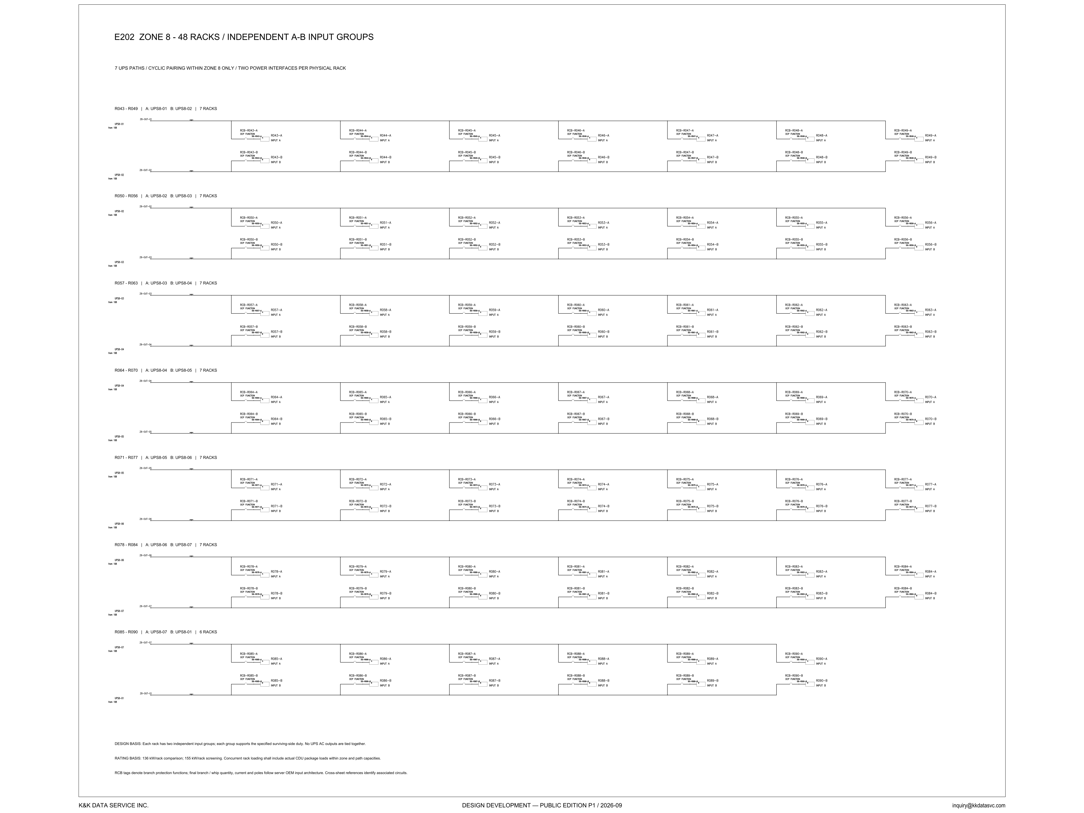
Seven headers walk 48 racks around seven UPS paths so each path is A for one group and B for another, and the last header, marked 6 racks, returns UPS8-01 as the B source.
Design Development — Public Edition P1: a reference design for study and evaluation, not a construction issue, not sealed by an Engineer of Record.
Scroll or pinch to zoom, drag to pan, click a highlighted device for its explanation. Vector drawing — it stays sharp at any magnification.
← E201 · All electrical sheets · E203 →
What this sheet shows
E202 is the Zone 8 rack diagram. The title reads 48 racks and independent A-B input groups. The subtitle states the rule the rest of the sheet draws: 7 UPS paths, cyclic pairing within Zone 8 only, and two power interfaces per physical rack. Seven headers divide the racks. Six of those headers are marked 7 racks, and the last header is marked 6 racks. R043 through R049 take A from UPS8-01 and B from UPS8-02. R050 through R056 take A from UPS8-02 and B from UPS8-03. R057 through R063 take A from UPS8-03 and B from UPS8-04. R064 through R070 take A from UPS8-04 and B from UPS8-05. R071 through R077 take A from UPS8-05 and B from UPS8-06. R078 through R084 take A from UPS8-06 and B from UPS8-07. R085 through R090 take A from UPS8-07 and B from UPS8-01. Under each header the sheet draws two horizontal feeders that do not join, the A feeder above the B feeder. Each column is one physical rack: INPUT A taps the upper feeder and INPUT B taps the lower feeder. On the last header the columns run from R085 to R090, and the sheet does not draw a seventh column on those two feeders.
Design intent you can read off the sheet
Read the seven headers down the sheet and each UPS name appears twice, once in an A column and once in a B column. UPS8-01 is A for R043 through R049 and B for R085 through R090. UPS8-02 is B for R043 through R049 and A for R050 through R056. UPS8-03 is B for R050 through R056 and A for R057 through R063. UPS8-04 is B for R057 through R063 and A for R064 through R070. UPS8-05 is B for R064 through R070 and A for R071 through R077. UPS8-06 is B for R071 through R077 and A for R078 through R084. UPS8-07 is B for R078 through R084 and A for R085 through R090. No header puts the same UPS on both inputs of the same racks. The two feeders under a header never join. That is the same statement as the design-basis note: each rack has two independent input groups, each group supports the specified surviving-side duty, and no UPS AC outputs are tied together. The header counts are not all equal. UPS8-02 through UPS8-06 are each named as A on a header marked 7 racks and as B on a header marked 7 racks. UPS8-01 is A on a header marked 7 racks and B on the header marked 6 racks. UPS8-07 is B on a header marked 7 racks and A on the header marked 6 racks. A header that does not name a UPS does not put that UPS on those racks. The subtitle keeps the cycle within Zone 8 only. The wrap is the last header: R085 through R090 is where UPS8-01 returns as a B source, and it returns inside Zone 8. No header on this sheet names a path outside UPS8-01 through UPS8-07. Keeping the UPS AC outputs from being tied is the sheet's own line on that point. The electrical architecture notes discuss what that separation does to the failure domain.
Tags, rating basis, and what is still open
The branch tag is RCB, then the rack, then A or B. At the first rack that is RCB-R043-A over R043-A, INPUT A, and RCB-R043-B over R043-B, INPUT B, and the block is marked OCP FUNCTION. The same pair is drawn at every rack through R090. The note under the diagram says what those tags are, and what they are not yet. RCB tags denote branch protection functions, and final branch and whip quantity, current and poles follow the server OEM input architecture. That selection is open on the sheet. The same note says cross-sheet references identify the associated circuits. Each feeder callout is that reference: the UPS name, the words from E108, and a Z8-OUT tag of the same index, from Z8-OUT-01 beside UPS8-01 to Z8-OUT-07 beside UPS8-07. Upstream of the callout, the path is not redrawn here. The rating note prints two different rack figures and labels the job of each. 136 kW/rack is the comparison figure. 155 kW/rack is the screening figure. Concurrent rack loading shall include actual CDU package loads within zone and path capacities. No CDU kilowatt is printed. The surviving-side duty named in the design-basis note is not given a kilowatt on this drawing either. A reader who takes 136 kW/rack as the entire electrical load of the rack has skipped the screening figure and the CDU sentence.
Status
The title block reads Design Development — Public Edition P1 / 2026-09. This is a reference design for study and evaluation, published with its assumptions and open items on the sheet. The pairing is drawn in full: seven groups, six of them marked 7 racks and the last marked 6 racks, two interfaces on every rack from R043 to R090, cyclic inside Zone 8, with the UPS AC outputs not tied. What the sheet does not close is the branch device, and the load arithmetic past the two named bases. Quantity, current and poles of the branch and the whip wait on the server OEM input architecture. The 136 kW/rack comparison, the 155 kW/rack screening, and the instruction to include CDU package loads are the rating basis, not a filled load schedule.
Sheet guide — the devices on this drawing
E202 title — cyclic pairing inside Zone 8
The drawing title fixes the subject: Zone 8, 48 racks, independent A-B input groups. The subtitle is the pairing rule itself: 7 UPS paths, cyclic pairing within Zone 8 only, and two power interfaces per physical rack. Everything below that line is the rule drawn out.
R043–R049 — A: UPS8-01, B: UPS8-02
The first header assigns R043 through R049, marked 7 racks, with A on UPS8-01 and B on UPS8-02. The upper feeder is the A path and the lower feeder is the B path, and each of these racks takes both. This is the start of the cycle, not one A bus and one B bus for the whole zone.
UPS8-01 / UPS8-02 — from E108, Z8-OUT
The left of each feeder names the UPS, notes that it is from E108, and carries a Z8-OUT tag of the same index: Z8-OUT-01 on the UPS8-01 feeder and Z8-OUT-02 on the UPS8-02 feeder. The one-line upstream of that callout is not redrawn on this sheet. The note below says cross-sheet references identify the associated circuits.
R043 — INPUT A and INPUT B
R043 is one physical rack with two interfaces on two feeders. The upper block is RCB-R043-A, marked OCP FUNCTION, and lands on R043-A, INPUT A, from UPS8-01. The lower block is RCB-R043-B, INPUT B, from UPS8-02. The two blocks do not share a bus.
R049 — seventh rack on the first feeders
R049 closes the first group. It is still one rack, with RCB-R049-A on the UPS8-01 feeder and RCB-R049-B on the UPS8-02 feeder, labeled INPUT A and INPUT B. The header's count of 7 racks is drawn across the sheet, through this last column.
R050–R056 — A: UPS8-02, B: UPS8-03
The second header steps both sources forward. A is UPS8-02, which was the B source for R043 through R049, and B is UPS8-03. Racks R050 through R056 are again marked 7 racks. One UPS name serving one group as B and the next group as A is the handoff the cycle is built from.
R078–R084 — A: UPS8-06, B: UPS8-07
R078 through R084 are marked 7 racks, A from UPS8-06 and B from UPS8-07. UPS8-06 is the B source on the header above, R071 through R077, whose A source is UPS8-05. The pairs keep moving. They do not settle into one fixed A side and one fixed B side for the hall. This header is still a group of 7. The short group is the one below it.
R085–R090 — A: UPS8-07, B: UPS8-01, 6 racks
The last header is what makes the pairing a cycle, and it is the short one. R085 through R090 are marked 6 racks, A from UPS8-07 and B from UPS8-01. UPS8-01, which opened the sheet as an A source, returns here as a B source, and it returns inside Zone 8. The row stops at R090. No seventh rack is drawn on these two feeders.
R090 — last rack, two interfaces
R090 is the last physical rack on the sheet, and it is still two interfaces rather than a remainder on a single path. RCB-R090-A, INPUT A, is on the UPS8-07 feeder. RCB-R090-B, INPUT B, is on the UPS8-01 feeder. The wrap is drawn at the rack, not only written in the header.
Sheet notes — duty, 136 and 155 kW/rack, RCB open
Three notes sit under the diagram. Each rack has two independent input groups, each group supports the specified surviving-side duty, and no UPS AC outputs are tied together. The rating line gives 136 kW/rack for comparison and 155 kW/rack for screening, and concurrent rack loading includes actual CDU package loads within zone and path capacities. RCB tags denote branch protection functions; final branch and whip quantity, current and poles follow the server OEM input architecture.
Get the full drawing set
This sheet is one page of the Electrical Drawing Book — Public Edition P1 (88 pages, 14 MB) — a direct PDF download with a published SHA-256 checksum, no registration. The complete coordinated set is on the downloads page. Background guides: data center one-line diagrams · GB300 NVL72 facility requirements · liquid cooling and CDU design.
Questions about any device or parameter on this sheet: inquiry@kkdatasvc.com or the contact page.