
Data Center Lab · Reference Designs · Network
Sheet N-002-EN: Hall key plan of 15 compute units and 10 central cabinets
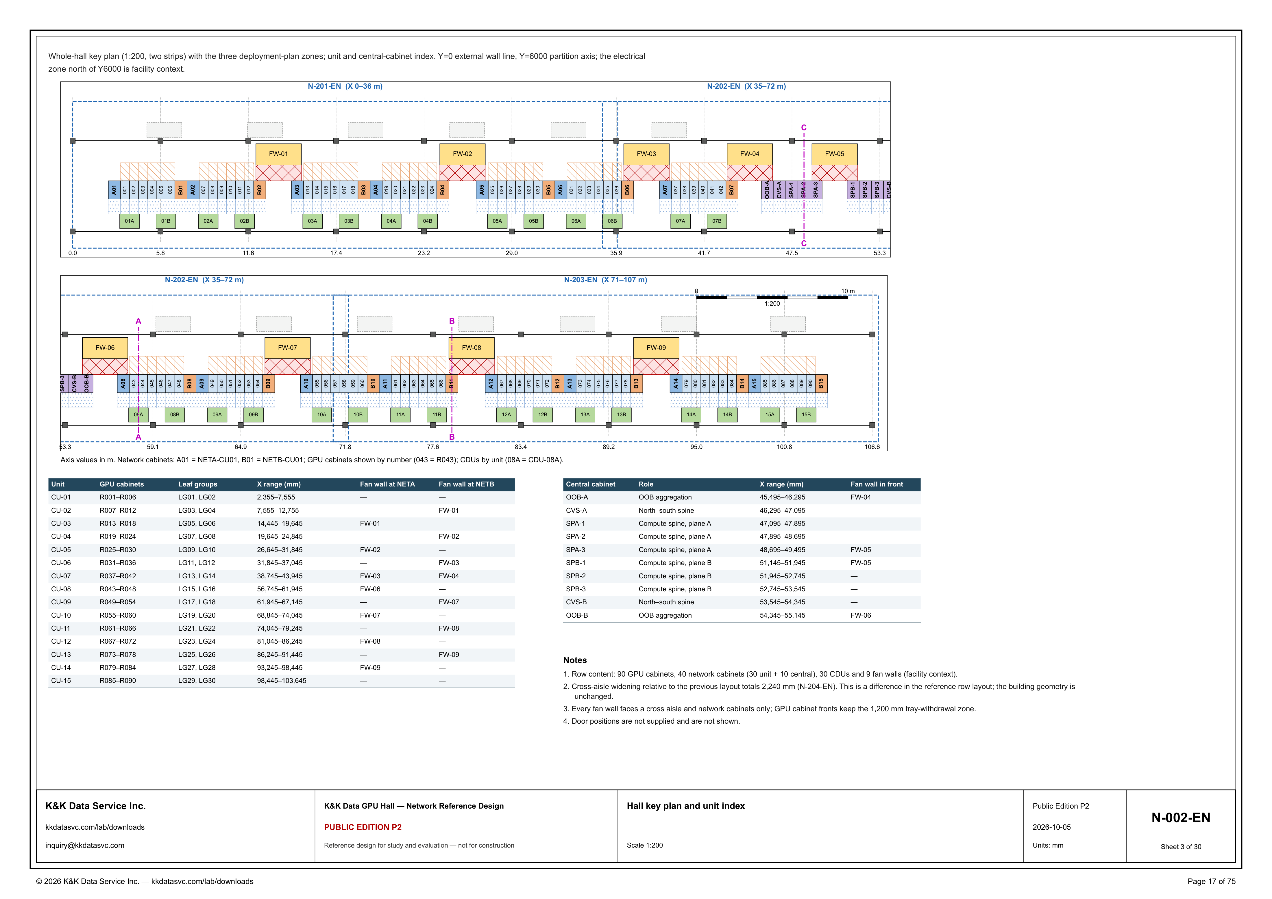
The hall's 15 compute units and 10 central cabinets are indexed on one 1:200 plan, and fan-wall names appear only where the index prints them.
Design Development — Public Edition P1: a reference design for study and evaluation, not a construction issue, not sealed by an Engineer of Record.
Scroll or pinch to zoom, drag to pan, click a highlighted device for its explanation. Vector drawing — it stays sharp at any magnification.
All network sheets · N-101-EN →
What this sheet shows
N-002-EN is the whole-hall key plan at scale 1:200, drawn as two strips. The upper strip carries deployment plan N-201-EN (X 0–36 m) and the part of N-202-EN (X 35–72 m) up to axis 53.3; axis labels on that strip run from 0.0 to 53.3. The lower strip resumes N-202-EN at the same 53.3 axis and carries N-203-EN (X 71–107 m) out to axis 106.6. N-202-EN is the zone drawn on both strips, because its printed range crosses that strip break. The zone callouts overlap at the joints: N-201-EN runs to 36 m and N-202-EN starts at 35 m; N-202-EN runs to 72 m and N-203-EN starts at 71 m. Under the plans, the unit index lists CU-01 through CU-15 and the central-cabinet index lists OOB-A through OOB-B. The legend fixes the abbreviations: A01 is NETA-CU01, B01 is NETB-CU01, a GPU number such as 043 is R043, and a CDU label such as 08A is CDU-08A. Axis values are in metres. The X-range column of each index is in millimetres. Y=0 is the external wall line and Y=6000 is the partition axis; the electrical zone north of Y6000 is facility context. Dashed lines labeled A and B cross the lower strip, and a dashed line labeled C crosses the upper strip through the central cabinets. The hall on this plan is the GPU hall in the GPU hall reference.
How the unit index is organized
Each unit row records the same facts, and CU-01 is the pattern: GPU cabinets R001–R006, leaf groups LG01 and LG02, X range 2,355–7,555 mm, and a dash for the fan wall at both NETA and NETB. On the strip that row is A01, cabinets 001 through 006, and B01, with CDUs 01A and 01B drawn with the unit. The X column shows which neighbors share an edge. The shared millimetre is printed on both rows: 7,555 between CU-01 and CU-02, 19,645 between CU-03 and CU-04, 31,845 between CU-05 and CU-06, 61,945 between CU-08 and CU-09, 74,045 between CU-10 and CU-11, 86,245 between CU-12 and CU-13, and 98,445 between CU-14 and CU-15. The next range starts later at 14,445, 26,645, 38,745, 68,845, 81,045 and 93,245 mm. The central-cabinet ranges fall in the opening between the units: CU-07 ends at 43,945 mm and CU-08 begins at 56,745 mm. CU-15 closes the index at R085–R090, leaf groups LG29 and LG30, X 98,445–103,645 mm, with a dash in both fan-wall columns. The leaf-group column names the groups that sit in the unit.
Central cabinets and the fan-wall rule
Ten central cabinets sit in X order inside the opening between CU-07 and CU-08. OOB-A, OOB aggregation, is 45,495–46,295 mm with FW-04 in front. CVS-A, North–south spine, is 46,295–47,095 mm. SPA-1, SPA-2 and SPA-3 are compute spine, plane A, at 47,095–47,895 mm, 47,895–48,695 mm and 48,695–49,495 mm, with FW-05 in front of SPA-3. SPB-1, SPB-2 and SPB-3 are compute spine, plane B, at 51,145–51,945 mm, 51,945–52,745 mm and 52,745–53,545 mm, with FW-05 also in front of SPB-1. SPA-3 ends at 49,495 mm; SPB-1 begins at 51,145 mm. CVS-B, North–south spine, is 53,545–54,345 mm, and OOB-B, OOB aggregation, is 54,345–55,145 mm with FW-06 in front. The strips share axis 53.3. The upper strip's central-cabinet labels run OOB-A, CVS-A, SPA-1, SPA-2, SPA-3, SPB-1, SPB-2, SPB-3 and CVS-B. CVS-B's range starts at 53,545 mm, after axis 53.3, and its label is printed on the upper strip. SPB-3's range, 52,745–53,545 mm, crosses axis 53.3, and the lower strip prints SPB-3, CVS-B and OOB-B at its left edge. Note 3 states the facing rule: every fan wall faces a cross aisle and network cabinets only, and GPU cabinet fronts keep the 1,200 mm tray-withdrawal zone. The index names several walls on two rows. FW-01 is the fan wall at NETB for CU-02 and at NETA for CU-03; FW-02, FW-03, FW-07, FW-08 and FW-09 are entered the same way. FW-04 is the NETB wall of CU-07 and the wall in front of OOB-A. FW-06 is the wall in front of OOB-B and the NETA wall of CU-08.
Status
The title block dates the sheet 2026-10-05 and issues it as Public Edition P2, number N-002-EN, sheet 3 of 30, scale 1:200, units millimetres. The status line reads as a reference design for study and evaluation, not for construction. Note 1 states the row content this plan indexes: 90 GPU cabinets, 40 network cabinets (30 unit + 10 central), 30 CDUs and 9 fan walls, and it marks the fan walls as facility context. Note 2 states that cross-aisle widening relative to the previous layout totals 2,240 mm (N-204-EN). The note calls that a difference in the reference row layout and states that the building geometry is unchanged. Note 4 is the open item, in the sheet's own words: door positions are not supplied and are not shown. The drawing set is the Public Edition P2 network reference design.
Sheet guide — the devices on this drawing
Plan datum — Y=0 wall and Y=6000 partition
The note above the strips sets the vertical datum: Y=0 is the external wall line and Y=6000 is the partition axis. The electrical zone north of Y6000 is facility context. The same note names the drawing as a whole-hall key plan at 1:200, in two strips, with the three deployment-plan zones and the unit and central-cabinet index.
CU-01 — A01, R001–R006, B01
First compute unit on the upper strip and the first index row: GPU cabinets R001–R006 between network cabinets A01 and B01, leaf groups LG01 and LG02, X range 2,355–7,555 mm. CDUs 01A and 01B are drawn with the unit. Both fan-wall columns are a dash, so no fan wall is named at NETA or at NETB for CU-01.
FW-01 — fan wall at CU-02 and CU-03
FW-01 is entered on two index rows: fan wall at NETB for CU-02, whose GPU range is R007–R012 and whose X range ends at 12,755 mm, and fan wall at NETA for CU-03, whose range starts at 14,445 mm. On the plan the wall sits on that cross-aisle interval. Note 3 says every fan wall faces a cross aisle and network cabinets only.
OOB-A to SPB-2 — central cabinets, upper strip
Central-cabinet row on the upper strip, after CU-07. In X order: OOB-A (OOB aggregation, FW-04 in front), CVS-A (North–south spine), SPA-1, SPA-2 and SPA-3 (compute spine, plane A, FW-05 in front of SPA-3), then SPB-1 and SPB-2 (compute spine, plane B, FW-05 also in front of SPB-1). The ranges run from 45,495 mm at OOB-A through 52,745 mm at the end of SPB-2. A dashed line labeled C crosses this row.
CU-08 — R043–R048 and the strip return
The lower strip opens at axis 53.3 with SPB-3, CVS-B and OOB-B, and with FW-06 in front of OOB-B. CU-08 follows at X 56,745–61,945 mm: network cabinet A08, GPU cabinets 043 through 048 (the legend's example, 043 = R043), B08, leaf groups LG15 and LG16, and CDUs 08A and 08B, where 08A is CDU-08A. FW-06 is also the fan wall at NETA for CU-08. A dashed line labeled A crosses this part of the strip.
Legend — A01, B01, 043 and 08A
The line under the strips locks the naming systems. Network cabinets are given by example: A01 is NETA-CU01 and B01 is NETB-CU01, and the strips label the series A01 through A15 and B01 through B15. GPU cabinets are drawn by number, so 043 on the plan is R043 in the index. CDUs are drawn by unit, so 08A is CDU-08A. Axis values are metres.
Unit index — CU-01 through CU-15
Fifteen rows, one per compute unit. Columns are the GPU-cabinet range, the leaf groups, the X range in millimetres, and the fan wall at NETA and at NETB. CU-01 opens the table at 2,355–7,555 mm with LG01 and LG02. CU-15 closes it at 98,445–103,645 mm with R085–R090 and LG29, LG30. A dash in a fan-wall cell means no wall is named on that face. These ranges are the coordinate source for the blocks on the strips.
Central index — OOB, CVS, SPA and SPB
Ten cabinets, each with a role, an X range in millimetres, and the fan wall in front. OOB-A and OOB-B are OOB aggregation. CVS-A and CVS-B are the North–south spines. SPA-1 through SPA-3 are compute spine, plane A; SPB-1 through SPB-3 are compute spine, plane B. Four rows name a fan wall: FW-04 at OOB-A, FW-05 at SPA-3, FW-05 at SPB-1, and FW-06 at OOB-B. The other rows carry a dash.
Notes 1–4 — counts, widening, facing, doors
Note 1 counts the row: 90 GPU cabinets, 40 network cabinets (30 unit + 10 central), 30 CDUs and 9 fan walls, with the fan walls marked facility context. Note 2 puts cross-aisle widening relative to the previous layout at 2,240 mm (N-204-EN) and states that this is a difference in the reference row layout; the building geometry is unchanged. Note 3 is the facing rule, including the 1,200 mm tray-withdrawal zone. Note 4: door positions are not supplied and are not shown.
Get the full drawing set
This sheet is one page of the GPU Hall Network Reference Design — Public Edition P2 (75 pages, 1.6 MB) — a direct PDF download with a published SHA-256 checksum, no registration. The complete coordinated set is on the downloads page. Background guides: data center one-line diagrams · GB300 NVL72 facility requirements · liquid cooling and CDU design.
Questions about any device or parameter on this sheet: inquiry@kkdatasvc.com or the contact page.