
Data Center Lab · Reference Designs · Network
Sheet N-101-EN: Dual-plane rail fabric from the tray NIC to the spine at 1.0:1
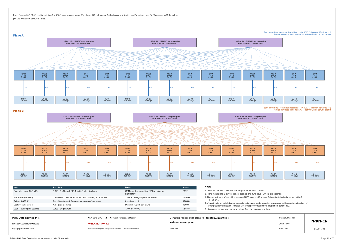
One drawing carries both compute planes: 120 leaves and 54 spines per plane at 1.0:1, the per-unit link figures, and the shared OSFP cage, where a NIC or cage failure affects both planes for that NIC.
Design Development — Public Edition P1: a reference design for study and evaluation, not a construction issue, not sealed by an Engineer of Record.
Scroll or pinch to zoom, drag to pan, click a highlighted device for its explanation. Vector drawing — it stays sharp at any magnification.
← N-002-EN · All network sheets · N-111-EN →
What this sheet shows
N-101-EN draws the compute fabric as two stacked planes. The line under the top border states that each ConnectX-8 800G port is split into 2 × 400G, one to each plane, and that each plane has 120 rail leaves (30 leaf groups × 4 rails) and 54 spines, with the leaf at 54 / 54 down/up (1:1). Those values are per the reference fabric summary. The upper plane, Plane A, runs from spine cabinets SPA-1, SPA-2 and SPA-3 through leaf cabinets NETA CU01 to NETA CU15 and into unit cabinets CU-01 to CU-15. The lower plane, Plane B, repeats the chain with SPB-1, SPB-2 and SPB-3, leaf cabinets NETB CU01 to NETB CU15, and the same CU-01 to CU-15 row. Every spine cabinet is marked 18 × SN5610 compute spine, each spine 120 × 400G down. Every leaf cabinet is marked 8 × CL, and every unit cabinet is marked 108 trays. A callout on each plane states that each unit cabinet → each spine cabinet is 144 × 400G (8 leaves × 18 spines × 1), and that the figures on the vertical links are the tray NIC → leaf 400G links per unit cabinet. Every one of those figures reads 432.
How the counts meet at 1:1
The diagram and the table are one port count written two ways. Per plane the table lists 1,620 compute trays and 6,480 CX-8 NICs, each NIC 1 × 400G into this plane, and it marks that row FACT, basis OEM rack documentation and the NVIDIA reference architecture. On one plane the fifteen unit cabinets are each marked 108 trays, and 15 × 108 is that 1,620. The vertical link above each is marked 432, and 15 × 432 equals the table's 6,480. Each of the 15 leaf cabinets is marked 8 × CL, and 15 × 8 is the table's 120 rail leaves (SN5610). The header gives that leaf as 54 / 54 down/up, and 8 × 54 down is the 432 under the cabinet. The leaf row also lists 20 unused (not reserved) ports per leaf against a basis of 128 × 400G logical ports per switch. The spine row lists 54 SN5610 switches, 120 ports used and 8 unused (not reserved) per spine, basis 3 cabinets × 18, which is the three cabinets drawn on the plane. Leaf oversubscription is 1.0:1 (non-blocking), basis the downlink / uplink port count. Leaf → spine uplink capacity is 2,592 Tb/s per plane, basis 120 × 54 × 400G. Note 1 states the two link totals for both planes together, and they are equal: NIC → leaf 12,960 and leaf → spine 12,960.
What stays separate, and what does not
Note 2 states the separation in a list: plane A and plane B leaves, spines, cabinets and trunk trays (TA / TB) are separate. Note 3 states the shared point: the two half-ports of one NIC share one OSFP cage, so a NIC or cage failure affects both planes for that NIC. The note cites N-103-EN for that statement. Note 4 then says what the unused ports are not: they are not dedicated expansion, storage or border capacity. Any assignment is a configuration item of the deploying organisation, checked with the capacity model of the supplement Section IS2. The leaf row and the spine row already mark those ports not reserved. Note 5 says the link counts per unit and per spine cabinet come from the reference port table. On this drawing those counts are the 144 × 400G in the callout and the 432 on each vertical link.
Status
The title block issues the drawing as Public Edition P2, number N-101-EN, sheet 4 of 30, dated 2026-10-05, scale NTS, units mm. Its status line reads: reference design for study and evaluation — not for construction. In the quantity table only the compute trays / CX-8 NICs row is marked FACT. The rows for rail leaves, spines, leaf oversubscription and leaf → spine uplink capacity are marked DESIGN. Note 4 leaves unused-port assignment as a configuration item of the deploying organisation, checked with the capacity model of supplement Section IS2. The sheet is part of the Public Edition P2 network reference design for the GPU hall reference.
Sheet guide — the devices on this drawing
ConnectX-8 — 800G port split, one 400G to each plane
The line under the border states that each ConnectX-8 800G port is split into 2 x 400G, one to each plane. Per plane it counts 120 rail leaves, written as 30 leaf groups x 4 rails, and 54 spines, with the leaf at 54 / 54 down/up (1:1). It says those values are per the reference fabric summary.
SPA-1 — 18 x SN5610 compute spine
SPA-1 is the left Plane A spine cabinet, marked 18 x SN5610 compute spine, each spine 120 x 400G down. SPA-2 and SPA-3 carry the same marking. The three cabinets are the table's spine basis of 3 cabinets x 18, the per-plane count of 54 spines.
144 x 400G — each unit cabinet to each spine cabinet
The Plane A callout states that each unit cabinet to each spine cabinet is 144 x 400G, written as 8 leaves x 18 spines x 1. The same callout defines the figures on the vertical links as tray NIC to leaf 400G links per unit cabinet, and each of those figures is 432. Plane B repeats both sentences.
NETA CU01 — 8 x CL, Plane A leaf cabinet
NETA CU01 is the first Plane A leaf cabinet, marked 8 x CL, and NETA CU02 through NETA CU15 repeat that mark. The per-plane table lists 120 rail leaves (SN5610), and 15 cabinets marked 8 x CL is that count. The box itself prints 8 x CL; the SN5610 name is the table's.
CU-01 — 108 trays and 432 NIC-to-leaf links
CU-01 is marked 108 trays. The vertical link above it is marked 432, which the callout defines as tray NIC to leaf 400G links per unit cabinet. CU-02 through CU-15 repeat both figures on this plane, and Plane B draws the same unit row with the same two figures.
SPB-1 — 18 x SN5610 compute spine, Plane B
SPB-1 is the left Plane B spine cabinet, marked 18 x SN5610 compute spine, each spine 120 x 400G down. SPB-2 and SPB-3 repeat that mark. Note 2 keeps these spines, and the Plane B leaves, cabinets and trunk trays, separate from Plane A.
NETB CU01 — 8 x CL, Plane B leaf cabinet
NETB CU01 is the first Plane B leaf cabinet, marked 8 x CL, and NETB CU02 through NETB CU15 repeat it. The vertical link under each is marked 432, the same tray NIC to leaf figure as on Plane A. Note 2 lists the leaves and cabinets of the two planes as separate.
Quantity table — per-plane FACT and DESIGN
Per plane, compute trays / CX-8 NICs are 1,620 / 6,480, each NIC 1 x 400G into this plane, and that row is marked FACT. Rail leaves are 120 with 54 / 54 down/up and 20 unused ports per leaf, and spines are 54 with 120 ports used and 8 unused per spine. Oversubscription is 1.0:1 and leaf-to-spine capacity is 2,592 Tb/s per plane, and those four rows are marked DESIGN.
Notes 1–5 — link totals, separation, OSFP cage
Note 1 counts NIC to leaf and leaf to spine at 12,960 each, for both planes. Note 2 keeps plane A and plane B leaves, spines, cabinets and trunk trays (TA / TB) separate, while note 3 states that the two half-ports of one NIC share one OSFP cage, so a NIC or cage failure affects both planes for that NIC (N-103-EN). Note 4 says unused ports are not dedicated expansion, storage or border capacity; any assignment is a configuration item of the deploying organisation, checked with the capacity model of the supplement Section IS2. Note 5 takes the per-unit and per-spine-cabinet link counts from the reference port table.
N-101-EN — title block, sheet 4 of 30
The title block gives the sheet title, Compute fabric: dual-plane rail topology, quantities and oversubscription, at scale NTS, and the number N-101-EN, sheet 4 of 30. The edition cell reads Public Edition P2, dated 2026-10-05, units mm. The status line reads: reference design for study and evaluation — not for construction.
Get the full drawing set
This sheet is one page of the GPU Hall Network Reference Design — Public Edition P2 (75 pages, 1.6 MB) — a direct PDF download with a published SHA-256 checksum, no registration. The complete coordinated set is on the downloads page. Background guides: data center one-line diagrams · GB300 NVL72 facility requirements · liquid cooling and CDU design.
Questions about any device or parameter on this sheet: inquiry@kkdatasvc.com or the contact page.