
Data Center Lab · Reference Designs · Network
Sheet N-121-EN: How the SN2201 management switches reach SN4600C aggregation and EXT-IF-OOB
OEM SN2201 switches in each GPU cabinet, and one SN2201 in each network cabinet, connect to SN4600C aggregation on sides A and B, with the per-strand pin map marked HOLD and addressing, upstream management and security zoning beyond EXT-IF-OOB left to the deploying organisation.
Design Development — Public Edition P1: a reference design for study and evaluation, not a construction issue, not sealed by an Engineer of Record.
Scroll or pinch to zoom, drag to pan, click a highlighted device for its explanation. Vector drawing — it stays sharp at any magnification.
← N-111-EN · All network sheets · N-201-EN →
What this sheet shows
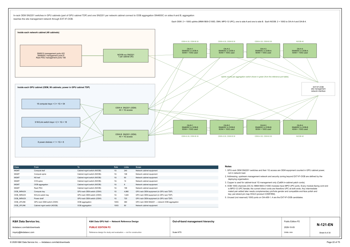
N-121-EN draws the out-of-band management hierarchy from the GPU cabinets and the network cabinets up to SN4600C aggregation on sides A and B. The line under the top border states it: in-rack OEM SN2201 switches in GPU cabinets (part of GPU cabinet TDP) and one SN2201 per network cabinet connect to OOB aggregation SN4600C on sides A and B, and aggregation reaches the site management network through EXT-IF-OOB. The same border gives the uplinks. Each OSW has 2 × 100G uplinks (MMA1B00-C100D, OM4, MPO-12 UPC), one to side A and one to side B, and each NOOB has 2 × 100G to OA-A-4 and OA-B-4. The upper block is inside each network cabinet (40 cabinets). It lists SN5610 management ports 422, SN4600C management ports 8 and rack PDU management ports 156, and it lands them on NOOB-xxx SN2201, 1 per cabinet (40). The lower block is inside each GPU cabinet (OEM, 90 cabinets; power in GPU cabinet TDP). It draws 18 compute trays × 3 × 1G = 54, 9 NVLink switch trays × 2 × 1G = 18, and 8 power shelves × 1 × 1G = 8 into OSW-A SN2201 (OEM) and OSW-B SN2201 (OEM), each marked 40 × 1G access. To the right, OA-A-1 through OA-A-4 are each marked SN4600C in OOB-A, and OA-B-1 through OA-B-4 are each marked SN4600C in OOB-B. The dashed box is EXT-IF-OOB, site management network interface. Green labels give the uplink count on each aggregation switch, and the caption says those counts are shown in green from the reference port table.
How the counts meet
The lower-left table is the same chain in three classes. MGMT is 1G to the cabinet mgmt switch (NOOB), scope network cabinet equipment: compute leaf 240, compute spine 108, NS leaf 60, CVS spine 14, OOB aggregation 8 and rack PDU 156. The block prints SN5610 management ports 422, and 240 + 108 + 60 + 14 = 422. It prints SN4600C management ports 8, the same count as the OOB aggregation row, and rack PDU management ports 156, the same count as the rack PDU row. OOB_INRACK is 1G to the GPU-rack OEM switch (OSW), scope GPU rack OEM equipment (in GPU rack TDP): compute tray 4,860, NVLink switch tray 1,620 and power shelf 720. The per-cabinet block is that basis across 90 cabinets: 54 × 90 = 4,860, 18 × 90 = 1,620 and 8 × 90 = 720. On one cabinet, 54 + 18 + 8 = 40 + 40, the two marks of 40 × 1G access. OOB_UPLINK is 100G. The GPU-rack OEM switch row is 360 links, scoped GPU rack OEM SN2201 → network OOB aggregation, and the cabinet mgmt switch row is 80 links. The border gives every OSW 2 × 100G, one to each side, and the green labels put both OSW families on the same switch: OSW-A 30, OSW-B 30 on OA-A-1, OA-A-2 and OA-A-3, and the same label on OA-B-1, OA-B-2 and OA-B-3. 30 + 30 = 60, the 60/64 × 100G used mark on each of those switches. 30 + 30 + 30 = 90, the GPU-cabinet count, for OSW-A into side A and again for OSW-B into side A; the B-side labels repeat it. 60 on OA-A-1, OA-A-2, OA-A-3, OA-B-1, OA-B-2 and OA-B-3 totals the table's 360. NOOB is placed apart from that: each NOOB's 2 × 100G goes to OA-A-4 and OA-B-4, each of those is labeled NOOB 40 and marked 40/64 × 100G used, and 40 + 40 = 80.
What the notes leave open
Note 1 draws the power boundary in the sheet's words: GPU-rack OEM SN2201 switches and their 1G access are OEM equipment counted in GPU cabinet power, not in network load. The GPU-cabinet title says the same equipment's power is in GPU cabinet TDP, and the OOB_INRACK scope column says GPU rack OEM equipment (in GPU rack TDP). Note 3 states that copper is used for cabinet-local 1G management only (Cat6A in-cabinet patch cords). Note 4 names the OOB 100G channels (OC-5). MMA1B00-C100D modules have MPO UPC ports. Every module-facing cord end is MPO-12 UPC female; the current direct cords are therefore UPC at both ends. Any intermediate mated pair added later needs complementary pin/hole gender and compatible end-face polish and key. The note then marks the open item: per-strand pin map HOLD (product CONFIRM). Note 5 says unused (not reserved) 100G ports on OA-A/B-1..4 are the EXT-IF-OOB candidates. The switches that carry the OSW labels are marked 60/64 × 100G used, and OA-A-4 and OA-B-4 are marked 40/64 × 100G used; the note names the unused ports as candidates. Note 2 places the next boundary at the dashed box: addressing, upstream management network and security zoning beyond EXT-IF-OOB are defined by the deploying organisation.
Status
The title block issues the drawing as Public Edition P2, number N-121-EN, sheet 8 of 30, dated 2026-10-05, scale NTS, units mm. The sheet title is Out-of-band management hierarchy. The status line reads: reference design for study and evaluation — not for construction. The open items are written on the sheet. Note 4 holds the per-strand pin map for product confirmation. Note 2 leaves addressing, the upstream management network and security zoning beyond EXT-IF-OOB to the deploying organisation. Note 5 names the unused (not reserved) 100G ports on OA-A/B-1..4 as the EXT-IF-OOB candidates. The sheet is part of the Public Edition P2 network reference design for the GPU hall reference.
Sheet guide — the devices on this drawing
SN5610 / SN4600C / PDU — management ports into NOOB
Inside each network cabinet (40 cabinets), the block lists SN5610 management ports 422, SN4600C management ports 8 and rack PDU management ports 156. The line from this block runs to NOOB-xxx. In the table, compute leaf 240, compute spine 108, NS leaf 60 and CVS spine 14 add to that 422, the OOB aggregation row is the 8, and the rack PDU row is 156.
NOOB-xxx — SN2201, one per network cabinet
NOOB-xxx is marked SN2201, 1 per cabinet (40). The border states that one SN2201 per network cabinet connects to OOB aggregation SN4600C on sides A and B, and that each NOOB has 2 × 100G to OA-A-4 and OA-B-4. The table counts those uplinks as 80 links at 100G, class OOB_UPLINK, from the cabinet mgmt switch (NOOB).
Compute, NVLink and power shelf — 1G endpoints
Inside each GPU cabinet (OEM, 90 cabinets; power in GPU cabinet TDP) the endpoint counts are 18 compute trays × 3 × 1G = 54, 9 NVLink switch trays × 2 × 1G = 18, and 8 power shelves × 1 × 1G = 8. The OOB_INRACK rows scale those counts across 90 cabinets: compute tray 4,860, NVLink switch tray 1,620 and power shelf 720, all at 1G to the GPU-rack OEM switch (OSW).
OSW-A / OSW-B — SN2201 (OEM), 40 × 1G access
Each GPU cabinet shows OSW-A SN2201 (OEM) and OSW-B SN2201 (OEM), each marked 40 × 1G access. The border gives each OSW 2 × 100G uplinks (MMA1B00-C100D, OM4, MPO-12 UPC), one to side A and one to side B. Note 1 states that these GPU-rack OEM SN2201 switches and their 1G access are counted in GPU cabinet power, not in network load.
OA-A-1 to OA-A-4 — SN4600C in OOB-A
OA-A-1, OA-A-2 and OA-A-3 are each marked SN4600C in OOB-A, 60/64 × 100G used, with the green label OSW-A 30, OSW-B 30. OA-A-4 is marked SN4600C in OOB-A, 40/64 × 100G used, with the green label NOOB 40. The caption says the uplink counts per aggregation switch are shown in green, from the reference port table.
OA-B-1 to OA-B-4 — SN4600C in OOB-B
OA-B-1, OA-B-2 and OA-B-3 repeat the A-side OSW label: each is marked SN4600C in OOB-B, 60/64 × 100G used, and each is labeled OSW-A 30, OSW-B 30. OA-B-4 is marked SN4600C in OOB-B, 40/64 × 100G used, and labeled NOOB 40. Together with OA-A-4, that is the border's statement that each NOOB has 2 × 100G to OA-A-4 and OA-B-4.
EXT-IF-OOB — site management network interface
The dashed box is labeled EXT-IF-OOB, site management network interface. The border states that aggregation reaches the site management network through EXT-IF-OOB. Note 2 states that addressing, the upstream management network and security zoning beyond EXT-IF-OOB are defined by the deploying organisation. Note 5 names the unused (not reserved) 100G ports on OA-A/B-1..4 as the candidates.
Link table — MGMT, OOB_INRACK and OOB_UPLINK
MGMT is 1G from compute leaf (240), compute spine (108), NS leaf (60), CVS spine (14), OOB aggregation (8) and rack PDU (156) to the cabinet mgmt switch (NOOB). OOB_INRACK is 1G from compute tray (4,860), NVLink switch tray (1,620) and power shelf (720) to the GPU-rack OEM switch (OSW). OOB_UPLINK is 100G: 360 from that OEM switch to OOB aggregation, and 80 from the cabinet mgmt switch (NOOB).
Notes 1–5 — power, copper, fiber and open items
Note 1 counts the GPU-rack OEM SN2201 switches and their 1G access in GPU cabinet power, not in network load. Note 3 limits copper to cabinet-local 1G management (Cat6A in-cabinet patch cords). Note 4 names OOB 100G channels (OC-5): MMA1B00-C100D modules have MPO UPC ports, every module-facing cord end is MPO-12 UPC female, and the per-strand pin map is HOLD (product CONFIRM). Note 5 says unused (not reserved) 100G ports on OA-A/B-1..4 are the EXT-IF-OOB candidates.
N-121-EN — title block, sheet 8 of 30
The title block gives the sheet title, Out-of-band management hierarchy, at scale NTS, and the number N-121-EN, sheet 8 of 30. The edition cell reads Public Edition P2, dated 2026-10-05, units mm. The status line reads: reference design for study and evaluation — not for construction.
Get the full drawing set
This sheet is one page of the GPU Hall Network Reference Design — Public Edition P2 (75 pages, 1.6 MB) — a direct PDF download with a published SHA-256 checksum, no registration. The complete coordinated set is on the downloads page. Background guides: data center one-line diagrams · GB300 NVL72 facility requirements · liquid cooling and CDU design.
Questions about any device or parameter on this sheet: inquiry@kkdatasvc.com or the contact page.