
Data Center Lab · Reference Designs · Network
Sheet N-203-EN: Network-cabinet coordinates and the FW-08 and FW-09 front zones on X 71–107 m
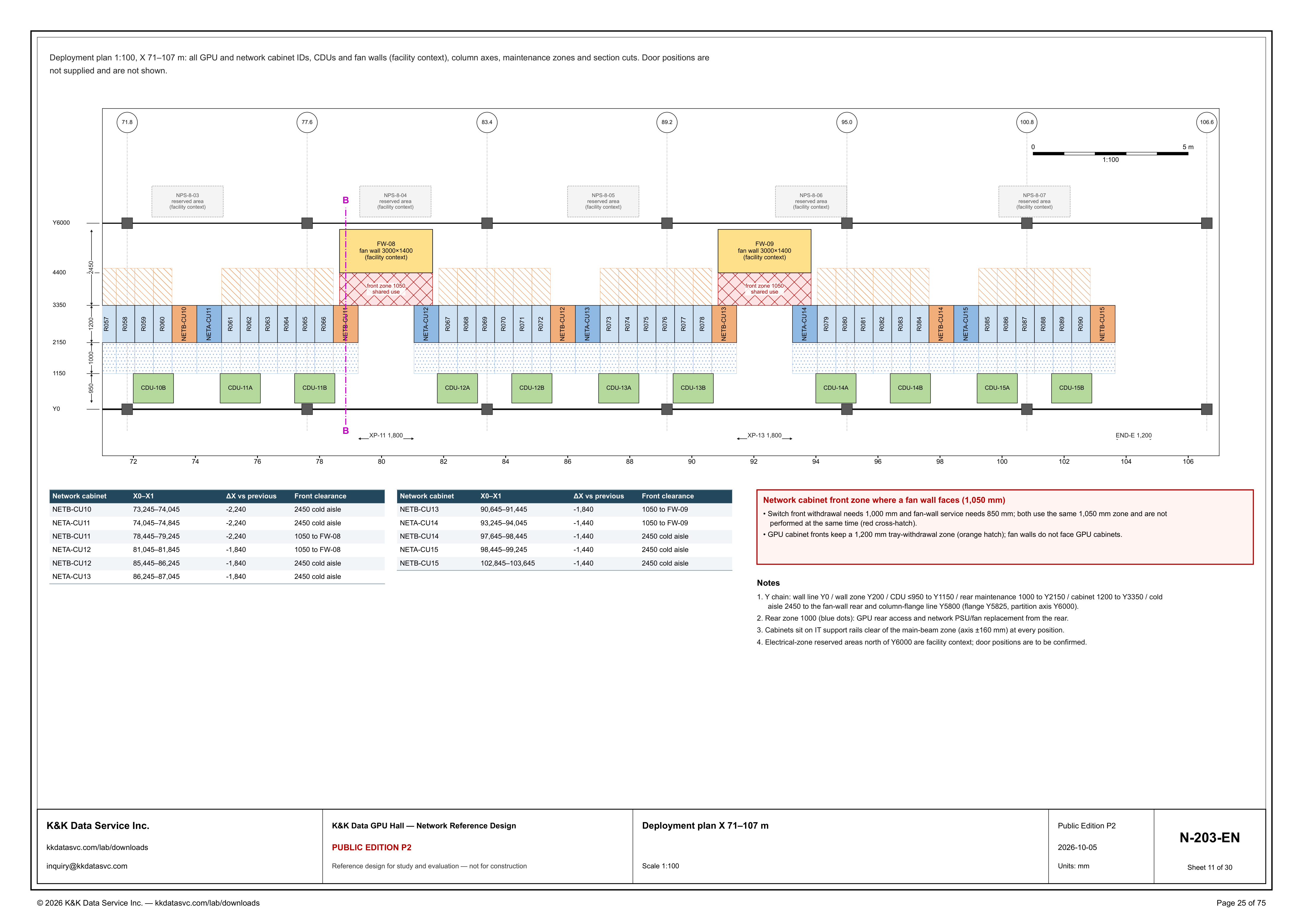
The X 71–107 m plan carries the row from R057 through NETB-CU15, and the table prints which network cabinets list 1050 to FW-08 or FW-09 and which keep a 2450 cold aisle.
Design Development — Public Edition P1: a reference design for study and evaluation, not a construction issue, not sealed by an Engineer of Record.
Scroll or pinch to zoom, drag to pan, click a highlighted device for its explanation. Vector drawing — it stays sharp at any magnification.
← N-202-EN · All network sheets · N-301-EN →
What this sheet shows
N-203-EN is the deployment plan at scale 1:100 for X 71–107 m. The line under the top border states the contents: all GPU and network cabinet IDs, CDUs and fan walls (facility context), column axes, maintenance zones and section cuts. That line also states that door positions are not supplied and are not shown. The drawn row runs from R057, R058, R059 and R060 through NETB-CU15. GPU cabinets R061–R066, R067–R072, R073–R078, R079–R084 and R085–R090 sit between the network cabinets. CDU-10B, CDU-11A, CDU-11B, CDU-12A, CDU-12B, CDU-13A, CDU-13B, CDU-14A, CDU-14B, CDU-15A and CDU-15B sit on the wall side of the row. FW-08 and FW-09 are each labeled fan wall 3000×1400 (facility context), with front zone 1050 and shared use. North of Y6000, NPS-8-03, NPS-8-04, NPS-8-05, NPS-8-06 and NPS-8-07 are each marked reserved area (facility context). Column-axis bubbles read 71.8, 77.6, 83.4, 89.2, 95.0, 100.8 and 106.6, the metre axis is marked 72, 74, 76, 78, 80, 82, 84, 86, 88, 90, 92, 94, 96, 98, 100, 102, 104 and 106, and a graphic scale of 5 m is marked 1:100. A dashed cut lettered B at both ends is drawn at NETB-CU11 and continues through CDU-11B. This is the X 71–107 m plan in the GPU hall reference.
Where each network cabinet sits
The tables give every network cabinet on this sheet an X0–X1 in the title block's millimetres. NETB-CU10 is 73,245–74,045. NETA-CU11 starts on that same 74,045 (74,045–74,845). R061 through R066 lie between NETA-CU11 and NETB-CU11 at 78,445–79,245. The plan prints XP-11 1,800 on the open interval after NETB-CU11, and NETA-CU12 is 81,045–81,845. R067 through R072 lie between NETA-CU12 and NETB-CU12 at 85,445–86,245. NETA-CU13 starts on that same 86,245 (86,245–87,045). R073 through R078 lie between NETA-CU13 and NETB-CU13 at 90,645–91,445. The plan prints XP-13 1,800 on the open interval after NETB-CU13, and NETA-CU14 is 93,245–94,045. R079 through R084 lie between NETA-CU14 and NETB-CU14 at 97,645–98,445. NETA-CU15 starts on that same 98,445 (98,445–99,245). R085 through R090 lie between NETA-CU15 and NETB-CU15 at 102,845–103,645. The plan prints END-E 1,200 after NETB-CU15. R057 through R060 are drawn before NETB-CU10. ΔX vs previous holds -2,240 from NETB-CU10 through NETB-CU11, -1,840 from NETA-CU12 through NETB-CU13, and -1,440 from NETA-CU14 through NETB-CU15. The value changes on NETA-CU12, the cabinet after the XP-11 interval, and on NETA-CU14, the cabinet after the XP-13 interval. Note 3 states the placement rule: cabinets sit on IT support rails clear of the main-beam zone (axis ±160 mm) at every position.
Front zones and the Y chain
Front clearance is printed on each network-cabinet row. The table gives 2450 cold aisle to NETB-CU10, NETA-CU11, NETB-CU12, NETA-CU13, NETB-CU14, NETA-CU15 and NETB-CU15. It gives 1050 to FW-08 to NETB-CU11 and NETA-CU12, and 1050 to FW-09 to NETB-CU13 and NETA-CU14. NETB-CU11 and NETA-CU12 are the cabinets on either side of the XP-11 interval, where FW-08 is drawn. NETB-CU13 and NETA-CU14 are the cabinets on either side of the XP-13 interval, where FW-09 is drawn. The callout names the fan-wall case: network cabinet front zone where a fan wall faces (1,050 mm). Switch front withdrawal needs 1,000 mm and fan-wall service needs 850 mm; both use the same 1,050 mm zone and are not performed at the same time, which the sheet marks with red cross-hatch. GPU cabinet fronts keep a 1,200 mm tray-withdrawal zone, marked with orange hatch, and the callout states that fan walls do not face GPU cabinets. Note 1 is the Y chain those zones sit in: wall line Y0, wall zone Y200, CDU ≤950 to Y1150, rear maintenance 1000 to Y2150, cabinet 1200 to Y3350, then cold aisle 2450 to the fan-wall rear and column-flange line Y5800 (flange Y5825, partition axis Y6000). Note 1's cabinet 1200 ends at Y3350. The callout's 1,200 mm is the orange tray-withdrawal zone at the GPU fronts. Note 2 names the rear zone 1000, drawn as blue dots, as GPU rear access and network PSU/fan replacement from the rear. The Y scale prints 4400 between 3350 and Y6000. Y3350 plus the callout's 1,050 mm is that printed 4400, and 4400 plus the 1400 in the fan-wall label 3000×1400 is the column-flange line Y5800. The same 1,050 mm plus 1400 is note 1's 2450, the cold aisle carried to the fan-wall rear.
Status
The title block dates the sheet 2026-10-05 and issues it as Public Edition P2, number N-203-EN, sheet 11 of 30, scale 1:100, units mm. The sheet title is Deployment plan X 71–107 m. The status line reads: reference design for study and evaluation — not for construction. The header says door positions are not supplied and are not shown. Note 4 says door positions are to be confirmed, and it states that electrical-zone reserved areas north of Y6000 are facility context. On the plan those areas are the boxes NPS-8-03, NPS-8-04, NPS-8-05, NPS-8-06 and NPS-8-07. FW-08 and FW-09 are marked facility context on the fan-wall labels. The drawing is part of the Public Edition P2 network reference design.
Sheet guide — the devices on this drawing
Y chain — wall Y0 to partition Y6000
The left-hand dimensions draw note 1. Wall line Y0 and wall zone Y200, CDU ≤950 to Y1150, rear maintenance 1000 to Y2150, cabinet 1200 to Y3350, then cold aisle 2450 to the fan-wall rear and column-flange line Y5800. The note gives flange Y5825 and partition axis Y6000. The scale beside the plan prints Y0, 1150, 2150, 3350, 4400 and Y6000, with the stacked dimensions 950, 1000, 1200 and 2450.
NETB-CU10 — R057–R060 and NETA-CU11
R057 through R060 are drawn before NETB-CU10, and NETA-CU11 starts on the 74,045 where NETB-CU10 ends. The table gives NETB-CU10 as 73,245–74,045 and NETA-CU11 as 74,045–74,845, both at ΔX -2,240 and both with front clearance 2450 cold aisle. CDU-10B is the wall-side unit at this end of the row, and orange hatch on the GPU fronts is the callout's 1,200 mm tray-withdrawal zone.
FW-08 — NETB-CU11 and NETA-CU12
NETB-CU11 is 78,445–79,245, ΔX -2,240, with front clearance 1050 to FW-08, and R061 through R066 lie between NETA-CU11 and that cabinet. The plan prints XP-11 1,800 on the open interval after NETB-CU11, and NETA-CU12 at 81,045–81,845 also lists 1050 to FW-08, at ΔX -1,840. FW-08 is labeled fan wall 3000×1400 (facility context), with front zone 1050 and shared use, and a dashed cut lettered B at both ends is drawn at NETB-CU11 and continues through CDU-11B.
NETB-CU12 — 2450 cold aisle with NETA-CU13
R067 through R072 lie between NETA-CU12 and NETB-CU12 at 85,445–86,245, and NETA-CU13 starts on that same 86,245 (86,245–87,045). Both network cabinets list front clearance 2450 cold aisle and ΔX -1,840. CDU-12A and CDU-12B sit on the wall side along R067 through R072.
FW-09 — NETB-CU13 and NETA-CU14
NETB-CU13 is 90,645–91,445 and lists 1050 to FW-09 at ΔX -1,840. R073 through R078 lie between NETA-CU13 and NETB-CU13, with CDU-13A and CDU-13B on the wall side, and the plan prints XP-13 1,800 on the open interval after NETB-CU13. NETA-CU14 is 93,245–94,045 and also lists 1050 to FW-09, at ΔX -1,440, and FW-09 is labeled fan wall 3000×1400 (facility context), with front zone 1050 and shared use.
NETB-CU14 — cold aisle through NETB-CU15
R079 through R084 lie between NETA-CU14 and NETB-CU14 at 97,645–98,445, and NETA-CU15 starts on that same 98,445 (98,445–99,245). R085 through R090 lie between NETA-CU15 and NETB-CU15 at 102,845–103,645, and the plan prints END-E 1,200 after NETB-CU15. NETB-CU14, NETA-CU15 and NETB-CU15 each list front clearance 2450 cold aisle and ΔX -1,440, with CDU-14A, CDU-14B, CDU-15A and CDU-15B on the wall side.
NPS-8-03 to NPS-8-05 — reserved areas
NPS-8-03, NPS-8-04 and NPS-8-05 are reserved-area boxes north of Y6000, each marked facility context, with column-axis bubbles 71.8, 77.6, 83.4 and 89.2 along the same band. Note 4 states that electrical-zone reserved areas north of Y6000 are facility context. The same note says door positions are to be confirmed.
NPS-8-06 and NPS-8-07 — reserved areas
NPS-8-06 and NPS-8-07 continue the reserved-area band north of Y6000, each marked facility context. The column-axis bubbles along this part of the plan read 95.0, 100.8 and 106.6, and the graphic scale of 5 m is marked 1:100. Note 4 groups these electrical-zone reserved areas with the others north of Y6000: facility context, with door positions to be confirmed.
Network-cabinet tables — X0–X1, ΔX, front clearance
The left table runs from NETB-CU10 at 73,245–74,045 through NETA-CU13 at 86,245–87,045. The right table runs from NETB-CU13 at 90,645–91,445 through NETB-CU15 at 102,845–103,645. The columns are X0–X1, ΔX vs previous, and front clearance. Front clearance is printed as 2450 cold aisle, as 1050 to FW-08, or as 1050 to FW-09.
Front-zone callout and notes 1–4
The callout states that switch front withdrawal needs 1,000 mm and fan-wall service needs 850 mm, that both use the same 1,050 mm zone, and that the two are not performed at the same time. GPU cabinet fronts keep a 1,200 mm tray-withdrawal zone, and fan walls do not face GPU cabinets. Note 1 is the Y chain, note 2 the rear zone 1000, note 3 the IT-rail clearance of the main-beam zone at axis ±160 mm, and note 4 the facility-context reserved areas with door positions to be confirmed.
Get the full drawing set
This sheet is one page of the GPU Hall Network Reference Design — Public Edition P2 (75 pages, 1.6 MB) — a direct PDF download with a published SHA-256 checksum, no registration. The complete coordinated set is on the downloads page. Background guides: data center one-line diagrams · GB300 NVL72 facility requirements · liquid cooling and CDU design.
Questions about any device or parameter on this sheet: inquiry@kkdatasvc.com or the contact page.