
Data Center Lab · Reference Designs · Network
Sheet N-502-EN: The highest fill drawn is TA at X49,095, at 25.5 %, and the trunk drop passes over TL
Six tray sections print the fill at each tray's maximum-occupancy station and at its median station, and the Y–Z view shows the TA trunk dropping over TL into the cabinet.
Design Development — Public Edition P1: a reference design for study and evaluation, not a construction issue, not sealed by an Engineer of Record.
Scroll or pinch to zoom, drag to pan, click a highlighted device for its explanation. Vector drawing — it stays sharp at any magnification.
← N-501-EN · All network sheets
What this sheet shows
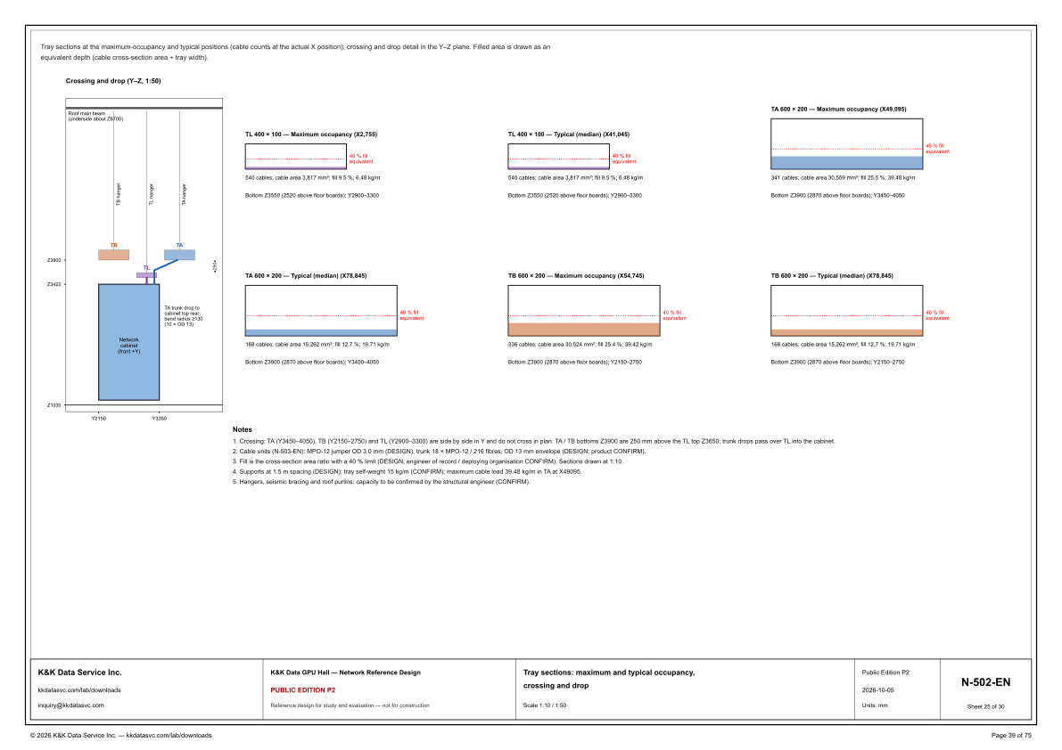
N-502-EN draws tray sections at the maximum-occupancy and typical positions, with cable counts at the actual X position, and the crossing and drop in the Y–Z plane. The line under the top border says the filled area is drawn as an equivalent depth: cable cross-section area ÷ tray width. The solid in each rectangle is that depth. Six sections are drawn at 1:10, and each one is marked 40 % fill equivalent. TL 400 × 100 is drawn at X2,755, titled maximum occupancy, and at X41,045, titled typical (median). TA 600 × 200 is drawn at X49,095, maximum occupancy, and at X78,845, typical (median). TB 600 × 200 is drawn at X54,745, maximum occupancy, and at X78,845, typical (median). Under each rectangle the sheet prints a cable count, a cable area, a fill and a load in kg/m, then a bottom elevation with a height above the floor boards, and a Y range. The left-hand view is titled Crossing and drop (Y–Z, 1:50). It draws the roof main beam, underside about Z6700, a TB hanger, a TL hanger and a TA hanger, the three trays, the network cabinet (front +Y), and the TA trunk drop. The title block names the drawing Tray sections: maximum and typical occupancy, crossing and drop, at scale 1:10 / 1:50, units mm.
Maximum and median, read across the six titles
The two TL sections print one line: 540 cables; cable area 3,817 mm²; fill 9.5 %; 6.48 kg/m, both at bottom Z3550 (2520 above floor boards), Y2900–3300. Maximum occupancy places that line at X2,755. Typical (median) places the same line at X41,045. The maximum-occupancy stations differ: TL at X2,755, TA at X49,095, TB at X54,745. The medians differ too: TA and TB are both at X78,845, and TL's median is X41,045. TA at X49,095 prints 341 cables; cable area 30,559 mm²; fill 25.5 %; 39.48 kg/m. TA at X78,845 prints 168 cables; cable area 15,262 mm²; fill 12.7 %; 19.71 kg/m. Both are bottom Z3900 (2870 above floor boards), Y3450–4050. TB at X54,745 prints 336 cables; cable area 30,524 mm²; fill 25.4 %; 39.42 kg/m. TB at X78,845 prints the same 168 cables, 15,262 mm², 12.7 % and 19.71 kg/m, at bottom Z3900 (2870 above floor boards), Y2150–2750. Twice that shared median is the TB maximum: 336 cables, 30,524 mm², 25.4 % and 39.42 kg/m. The TA maximum prints 341 cables, 30,559 mm², 25.5 % and 39.48 kg/m, each above the doubled median. Note 4 names the maximum cable load as 39.48 kg/m in TA at X49095, the title's X49,095 without the thousands comma, and that is the largest load on the sheet. TL's 540 cables are the largest count, on 3,817 mm². TA's maximum puts 341 cables on 30,559 mm². Note 2 defines the units, on N-503-EN. The Y–Z callout names the TA drop as a trunk drop.
Side by side in Y, and the drop over TL
Note 1 says TA (Y3450–4050), TB (Y2150–2750) and TL (Y2900–3300) are side by side in Y and do not cross in plan. TB ends at Y2750, TL runs Y2900–3300, and TA starts at Y3450. Each Y span equals the first figure of the tray size: Y3450–4050 is the 600 of TA 600 × 200, Y2150–2750 is the 600 of TB 600 × 200, and Y2900–3300 is the 400 of TL 400 × 100. The same note says TA / TB bottoms Z3900 are 250 mm above the TL top Z3650, and that trunk drops pass over TL into the cabinet. TL prints bottom Z3550, and Z3650 is 100 mm above that bottom, the second figure of 400 × 100. 3900 minus 3650 is the stated 250 mm, and the 1:50 view dimensions that 250 beside the trays. The view draws TB, TL and TA in increasing Y, with the cabinet labeled network cabinet (front +Y). Y2150 is marked at one end and Y3350 further along the bottom. Z3900 is at the TA/TB line, Z3422 at the top of the cabinet outline, and Z1030 at the bottom of the view. Both heights above the floor boards return to that Z1030: 3550 minus 2520, and 3900 minus 2870. The drop callout reads: TA trunk drop to cabinet top rear; bend radius ≥130 (10 × OD 13). Note 2's trunk is 18 × MPO-12 / 216 fibres, OD 13 mm envelope (DESIGN; product CONFIRM), and the callout writes ≥130 as 10 × that OD 13. Note 3 calls fill the cross-section area ratio with a 40 % limit (DESIGN; engineer of record / deploying organisation CONFIRM), sections drawn at 1:10. The printed fills are 9.5 % on both TL sections, 25.5 % on TA at X49,095, 25.4 % on TB at X54,745, and 12.7 % on the medians at X78,845. Each 40 % fill equivalent line sits above the filled depth.
Status
The title block places this drawing in the K&K Data GPU Hall — Network Reference Design and marks it Public Edition P2. The number is N-502-EN, sheet 25 of 30, dated 2026-10-05, scale 1:10 / 1:50, units mm. The status line reads: reference design for study and evaluation — not for construction. Sheet 25 of 30 is the sheet line in the title block. The line under the border reads Page 39 of 75. Note 2 sends the cable units to N-503-EN: an MPO-12 jumper, OD 3.0 mm (DESIGN), and a trunk of 18 × MPO-12 / 216 fibres, OD 13 mm envelope (DESIGN; product CONFIRM). Note 4 sets supports at 1.5 m spacing (DESIGN), marks tray self-weight 15 kg/m as CONFIRM, and states the maximum cable load as 39.48 kg/m in TA at X49095. Note 5 reads: hangers, seismic bracing and roof purlins: capacity to be confirmed by the structural engineer (CONFIRM). The 1:50 view draws the TB hanger, the TL hanger and the TA hanger, and it labels the roof main beam underside about Z6700. The word on that beam is about. The sheet is part of the Public Edition P2 network reference design for the GPU hall reference.
Sheet guide — the devices on this drawing
Header — counts at the X station, fill as equivalent depth
The line under the top border says these are tray sections at the maximum-occupancy and typical positions, with cable counts at the actual X position, and the crossing and drop in the Y–Z plane. Filled area is drawn as an equivalent depth: cable cross-section area ÷ tray width. The solid in each of the six rectangles is that depth.
TB, TL, TA — bottoms Z3900 are 250 mm above the TL top
The view is titled Crossing and drop (Y–Z, 1:50). It draws TB, TL and TA in Y order under the roof main beam, underside about Z6700, each from its hanger. Note 1 says the three trays are side by side in Y and do not cross in plan, and that TA / TB bottoms Z3900 are 250 mm above the TL top Z3650. The 250 is dimensioned on this view. Trunk drops pass over TL into the cabinet.
Network cabinet — TA trunk drop, bend radius ≥130
The cabinet is labeled network cabinet (front +Y). The callout reads: TA trunk drop to cabinet top rear; bend radius ≥130 (10 × OD 13). Note 2 defines that trunk as 18 × MPO-12 / 216 fibres, OD 13 mm envelope, and marks the envelope DESIGN, product CONFIRM. The view prints Z3422 at the top of the cabinet outline and Z1030 at the bottom, with Y2150 and Y3350 along that bottom.
TL 400 × 100 — maximum occupancy at X2,755
The maximum-occupancy section for TL is at X2,755 and prints 540 cables, cable area 3,817 mm², fill 9.5 %, 6.48 kg/m. Bottom Z3550 (2520 above floor boards), Y2900–3300. The 40 % fill equivalent line is drawn above that filled depth. The typical section at X41,045 prints this same count, area, fill and load.
TL 400 × 100 — typical (median) at X41,045
The typical (median) station for TL is X41,045. The line under the rectangle matches the maximum-occupancy section: 540 cables, cable area 3,817 mm², fill 9.5 %, 6.48 kg/m, bottom Z3550 (2520 above floor boards), Y2900–3300. These two titles are the X stations the sheet draws for TL.
TA 600 × 200 — maximum occupancy at X49,095
TA's maximum-occupancy section is at X49,095: 341 cables, cable area 30,559 mm², fill 25.5 %, 39.48 kg/m. Bottom Z3900 (2870 above floor boards), Y3450–4050. Note 4 names this load as the maximum cable load and writes the station X49095. The 40 % fill equivalent line is drawn above the filled depth. Note 3 marks the 40 % limit DESIGN, for the engineer of record / deploying organisation to CONFIRM.
TA 600 × 200 — typical (median) at X78,845
At X78,845 the TA section prints 168 cables, cable area 15,262 mm², fill 12.7 %, 19.71 kg/m, bottom Z3900 (2870 above floor boards), Y3450–4050. Twice that row is 336 cables, 30,524 mm², 25.4 % and 39.42 kg/m, which is the TB maximum at X54,745. TA's own maximum, at X49,095, prints 341 cables, 30,559 mm², 25.5 % and 39.48 kg/m.
TB 600 × 200 — maximum occupancy at X54,745
TB's maximum-occupancy station is X54,745. The section prints 336 cables, cable area 30,524 mm², fill 25.4 %, 39.42 kg/m, bottom Z3900 (2870 above floor boards), Y2150–2750. That row is twice the median row TA and TB both print at X78,845. Note 4 names TA's 39.48 kg/m at X49095 as the maximum cable load.
TB 600 × 200 — typical (median) at X78,845
TB's median station is the same X78,845 as TA's median, and the figures match TA's median: 168 cables, cable area 15,262 mm², fill 12.7 %, 19.71 kg/m. The Y range is TB's own, Y2150–2750, and the bottom is Z3900 (2870 above floor boards). The title size is 600 × 200, the same size printed on TA.
Notes 1–5 — separation, units, fill, supports, structure
Note 1 is the Y separation and the 250 mm above the TL top. Note 2 points the cable units to N-503-EN and marks the trunk OD 13 mm envelope product CONFIRM. Note 3 is the 40 % area-ratio limit, DESIGN, for the engineer of record / deploying organisation to CONFIRM, with sections at 1:10. Note 4 is supports at 1.5 m (DESIGN), tray self-weight 15 kg/m (CONFIRM), and 39.48 kg/m in TA at X49095. Note 5 leaves the capacity of the hangers, seismic bracing and roof purlins with the structural engineer (CONFIRM).
Get the full drawing set
This sheet is one page of the GPU Hall Network Reference Design — Public Edition P2 (75 pages, 1.6 MB) — a direct PDF download with a published SHA-256 checksum, no registration. The complete coordinated set is on the downloads page. Background guides: data center one-line diagrams · GB300 NVL72 facility requirements · liquid cooling and CDU design.
Questions about any device or parameter on this sheet: inquiry@kkdatasvc.com or the contact page.