
Data Center Lab · Reference Designs · Network
Sheet N-501-EN: Plane-A trunks use TA only, plane-B trunks use TB only, and power and water stay below the floor
Plane-A trunks use TA only and plane-B trunks use TB only, while NIC and DPU jumpers of both planes stay on TL, and the wet and power channels are under the floor.
Design Development — Public Edition P1: a reference design for study and evaluation, not a construction issue, not sealed by an Engineer of Record.
Scroll or pinch to zoom, drag to pan, click a highlighted device for its explanation. Vector drawing — it stays sharp at any magnification.
← N-401-EN · All network sheets · N-502-EN →
What this sheet shows
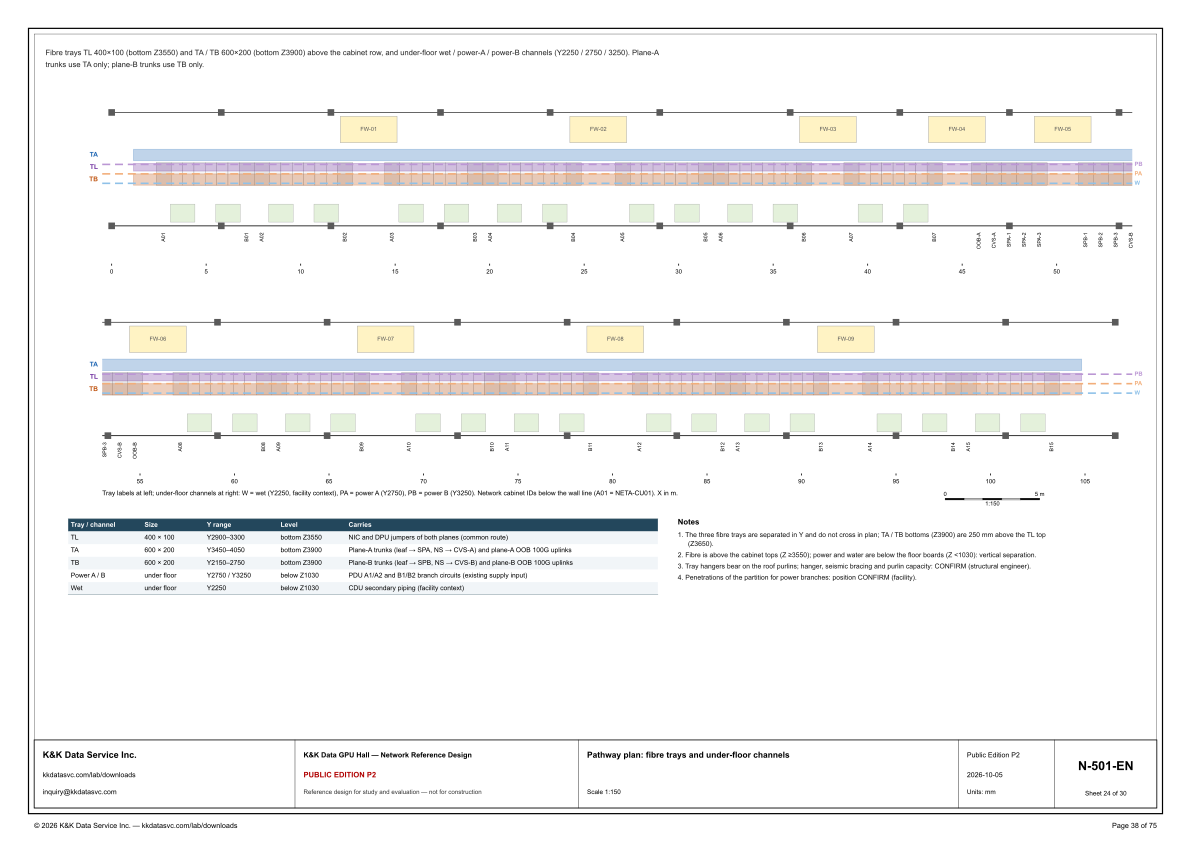
N-501-EN is the pathway plan, scale 1:150, units mm. The sentence under the top border states the drawing: fibre trays TL 400×100 (bottom Z3550) and TA / TB 600×200 (bottom Z3900) above the cabinet row, and under-floor wet / power-A / power-B channels (Y2250 / 2750 / 3250). The same sentence states the trunk rule: plane-A trunks use TA only; plane-B trunks use TB only. The row is drawn as two lengths along X. The upper length is scaled from 0 to 50. It prints A01, B01, A02, B02, A03, B03, A04, B04, A05, B05, A06, B06, A07 and B07, then OOB-A, CVS-A, SPA-1, SPA-2, SPA-3, SPB-1, SPB-2, SPB-3 and CVS-B, with FW-01, FW-02, FW-03, FW-04 and FW-05 above the trays. The lower length is scaled from 55 to 105. It prints SPB-3 and CVS-B again, then OOB-B, then A08, B08, A09, B09, A10, B10, A11, B11, A12, B12, A13, B13, A14, B14, A15 and B15, with FW-06, FW-07, FW-08 and FW-09 above the trays. A bar at the right of the lower scale reads 0 to 5 m and is marked 1:150. The caption under the scales reads: tray labels at left; under-floor channels at right: W = wet (Y2250, facility context), PA = power A (Y2750), PB = power B (Y3250). Network cabinet IDs are below the wall line, and the caption expands the first of them: A01 = NETA-CU01. The axis is marked X in m, while the title block sets the units to mm.
Separation in Y and in Z
The schedule at the lower left gives every route a size, a Y range, a level and what it carries. TL is 400 × 100, Y2900–3300, bottom Z3550. TA is 600 × 200, Y3450–4050, bottom Z3900. TB is 600 × 200, Y2150–2750, bottom Z3900. Power A / B is under floor, Y2750 / Y3250, below Z1030. Wet is under floor, Y2250, below Z1030. Note 1 is only about the three fibre trays: they are separated in Y and do not cross in plan. The printed ranges do not overlap one another. TB ends at Y2750, TL runs Y2900–3300, and TA starts at Y3450. The same note states that figure: TA / TB bottoms (Z3900) are 250 mm above the TL top (Z3650). Note 2 separates fibre from power and water by elevation: fibre is above the cabinet tops (Z ≥3550); power and water are below the floor boards (Z <1030): vertical separation. The Y column still needs a close reading against that note. Wet at Y2250 falls within TB's printed range Y2150–2750. Power A is printed at Y2750, the end figure of that same TB range. Power B at Y3250 falls within TL's printed range Y2900–3300. Y2250, Y2750 and Y3250 all sit outside TA's range Y3450–4050. Note 1 does not say the under-floor channels miss the trays in plan. It says the three fibre trays do not cross one another. The vertical separation is the statement in note 2.
What each route carries
The Carries column is the routing rule this plan is drawn to show. TL carries NIC and DPU jumpers of both planes (common route). TA carries plane-A trunks (leaf → SPA, NS → CVS-A) and plane-A OOB 100G uplinks. TB carries plane-B trunks (leaf → SPB, NS → CVS-B) and plane-B OOB 100G uplinks. The header states the trunk limit in those words: plane-A trunks use TA only, and plane-B trunks use TB only. The limit is on trunks. It does not take the NIC and DPU jumpers off TL. The cabinet IDs named in the trunk descriptions are printed on the plan. After B07, the upper length reads OOB-A, CVS-A, SPA-1, SPA-2, SPA-3, SPB-1, SPB-2, SPB-3 and CVS-B. The lower length opens on SPB-3 and CVS-B again, then OOB-B, then A08, B08 through A15, B15. The trays are drawn as bands along both lengths, labeled TA, TL and TB at the left of each length. The caption gives a long name for a single ID: A01 = NETA-CU01. It does not print long names for the other A and B IDs on this sheet. Power A / B carries PDU A1/A2 and B1/B2 branch circuits (existing supply input). Wet carries CDU secondary piping (facility context).
Status
The title block names this drawing Pathway plan: fibre trays and under-floor channels, in the K&K Data GPU Hall — Network Reference Design, and marks it Public Edition P2. The number is N-501-EN, sheet 24 of 30, dated 2026-10-05, scale 1:150, units mm. The status line reads: reference design for study and evaluation — not for construction. Two notes are left open on the sheet. Note 3 says tray hangers bear on the roof purlins, and marks hanger, seismic bracing and purlin capacity CONFIRM (structural engineer). Note 4 marks penetrations of the partition for power branches as position CONFIRM (facility). The wet route is marked facility context twice: in the schedule, as CDU secondary piping, and in the caption, as W = wet at Y2250. Nothing on this sheet closes those CONFIRM items. The sheet is part of the Public Edition P2 network reference design for the GPU hall reference.
Sheet guide — the devices on this drawing
Header — plane-A trunks on TA only, plane-B on TB only
The sentence under the top border names the trays and the channels together: TL 400×100 at bottom Z3550, TA / TB 600×200 at bottom Z3900, and the under-floor channels at Y2250 / 2750 / 3250. The trunk rule is in that same sentence: plane-A trunks use TA only; plane-B trunks use TB only.
TA, TL, TB — fibre trays on the upper length
The left-hand labels on the upper length are TA, TL and TB. TA is the upper band, TL the middle band and TB the lower band. Note 1 says these three fibre trays are separated in Y and do not cross in plan. The schedule places TA at Y3450–4050, TL at Y2900–3300 and TB at Y2150–2750. TA and TB bottoms are Z3900. The TL bottom is Z3550, and note 1 names the TL top as Z3650.
FW-01 and FW-02 — boxes above the upper trays
FW-01 and FW-02 are the first boxes on the line above the upper tray bands. The same upper length continues with FW-03, FW-04 and FW-05. The lower length carries FW-06, FW-07, FW-08 and FW-09 above its trays. This plan prints those FW identifiers on the boxes. It does not print a size for them.
A01 — NETA-CU01, below the wall line
The caption says the network cabinet IDs are below the wall line, and it gives one expansion: A01 = NETA-CU01. On the upper length the IDs begin A01, B01, A02, B02 and run on through the A and B pairs to B07. This sheet does not print a long name for B01 or for the later pairs.
OOB-A through CVS-B — cabinets named for the trunks
After B07 the upper length prints OOB-A, CVS-A, SPA-1, SPA-2, SPA-3, SPB-1, SPB-2, SPB-3 and CVS-B. Plane-A trunks are leaf → SPA and NS → CVS-A, on TA only, with the plane-A OOB 100G uplinks. Plane-B trunks are leaf → SPB and NS → CVS-B, on TB only, with the plane-B OOB 100G uplinks.
OOB-B — lower length, with SPB-3, CVS-B, FW-06 and FW-07
The lower length begins with SPB-3 and CVS-B, the same two IDs that close the upper length, then OOB-B, then A08. The scale under this length is marked from 55 onward. FW-06 and FW-07 are the boxes above this part of the trays. OOB-B is printed here. OOB-A is printed on the upper length and is not repeated on this length.
W, PA, PB — under-floor channels at the right
The caption decodes the right-hand marks: W = wet (Y2250, facility context), PA = power A (Y2750), PB = power B (Y3250). The schedule puts power and wet under the floor, below Z1030. Wet carries CDU secondary piping (facility context). Power A / B carries PDU A1/A2 and B1/B2 branch circuits (existing supply input).
Schedule — size, Y range, level and carries
The rows are TL, TA, TB, Power A / B and Wet. TL is 400 × 100, Y2900–3300, bottom Z3550, NIC and DPU jumpers of both planes (common route). TA is 600 × 200, Y3450–4050, bottom Z3900, plane-A trunks (leaf → SPA, NS → CVS-A) and plane-A OOB 100G uplinks. TB is 600 × 200, Y2150–2750, bottom Z3900, plane-B trunks (leaf → SPB, NS → CVS-B) and plane-B OOB 100G uplinks. Power A / B is Y2750 / Y3250, below Z1030. Wet is Y2250, below Z1030.
Notes 1–4 — separation, and the open CONFIRM items
Note 1: the three fibre trays are separated in Y and do not cross in plan; TA / TB bottoms (Z3900) are 250 mm above the TL top (Z3650). Note 2: fibre is above the cabinet tops (Z ≥3550); power and water are below the floor boards (Z <1030): vertical separation. Note 3 marks hanger, seismic bracing and purlin capacity CONFIRM (structural engineer). Note 4 marks partition penetrations for power branches as position CONFIRM (facility).
Get the full drawing set
This sheet is one page of the GPU Hall Network Reference Design — Public Edition P2 (75 pages, 1.6 MB) — a direct PDF download with a published SHA-256 checksum, no registration. The complete coordinated set is on the downloads page. Background guides: data center one-line diagrams · GB300 NVL72 facility requirements · liquid cooling and CDU design.
Questions about any device or parameter on this sheet: inquiry@kkdatasvc.com or the contact page.