
Data Center Lab · Reference Designs · Network
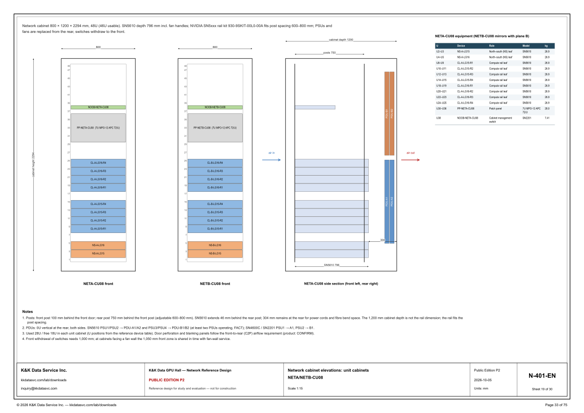
Sheet N-401-EN: NETA-CU08 lists SN5610 leaves, a 7U MPO-12 patch and an SN2201 by U, and NETB-CU08 mirrors that equipment on plane B
The unit-cabinet elevation shows where the north–south leaves, the compute rail leaves, the 7U MPO-12 patch and the SN2201 sit in NETA-CU08, and the table says NETB-CU08 mirrors that equipment with plane B.
Design Development — Public Edition P1: a reference design for study and evaluation, not a construction issue, not sealed by an Engineer of Record.
Scroll or pinch to zoom, drag to pan, click a highlighted device for its explanation. Vector drawing — it stays sharp at any magnification.
← N-313-EN · All network sheets · N-501-EN →
What this sheet shows
N-401-EN is the unit-cabinet elevation, drawn at 1:15. It shows a front elevation of NETA-CU08, a front elevation of NETB-CU08, and one side section captioned NETA-CU08 side section (front left, rear right). The table at the upper right is titled NETA-CU08 equipment (NETB-CU08 mirrors with plane B). The sentence under the top border states the cabinet once: 800 × 1200 × 2294 mm, 48U (46U usable). The NETA elevation carries the vertical dimension cabinet height 2294, and both fronts are dimensioned 800 wide. The side section prints cabinet depth 1200, posts 750, SN5610 796 and a rear dimension of 304. That border sentence also gives the switch depth as 796 mm including fan handles, names NVIDIA SN5xxx rail kit 930-9SKIT-00L0-00A as fitting post spacing 600–800 mm, and states how the cabinet is serviced: PSUs and fans are replaced from the rear, switches withdraw to the front. Beside each front, the U scale prints 48 at the top and the odd numbers from 47 down through 1. Units are mm.
What occupies the U
The table lists the occupied U in NETA-CU08, and the front elevation draws those devices on the same ranges. U2–U3 is NS-A-LG15 and U4–U5 is NS-A-LG16, each a North–south (NS) leaf, model SN5610, 26.9 kg. The LG15 compute rail leaves are CL-A-LG15-R1 on U8–U9, CL-A-LG15-R2 on U10–U11, CL-A-LG15-R3 on U12–U13 and CL-A-LG15-R4 on U14–U15, each an SN5610 at 26.9 kg. The LG16 compute rail leaves are CL-A-LG16-R1 on U18–U19, CL-A-LG16-R2 on U20–U21, CL-A-LG16-R3 on U22–U23 and CL-A-LG16-R4 on U24–U25, again SN5610 at 26.9 kg. U30–U36 is PP-NETA-CU08, role patch panel, model 7U MPO-12 APC 72/U, 28.0 kg. U38 is NOOB-NETA-CU08, role cabinet management switch, model SN2201, 7.41 kg. The elevation draws no device after U5 and before U8, after U15 and before U18, after U25 and before U30, or after U36 and before U38, and the table lists no device above U38. Note 3 states used 28U / free 18U in each unit cabinet, with U positions taken from this reference device table. The note's used 28U and free 18U add to 46, the usable count written as 48U (46U usable). The NETB front repeats the bands with plane-B IDs: NS-B-LG15, NS-B-LG16, CL-B-LG15-R1 through CL-B-LG15-R4, CL-B-LG16-R1 through CL-B-LG16-R4, PP-NETB-CU08 (7U MPO-12 APC 72/U) and NOOB-NETB-CU08. The table does not reprint those B rows; its title says NETB-CU08 mirrors with plane B.
Depth, PDUs, airflow and the front zone
Note 1 separates the cabinet depth from the rail. The front post is 100 mm behind the front door, and the rear post is 750 mm behind the front post, adjustable 600–800 mm. The SN5610 extends 46 mm behind the rear post, and 304 mm remains at the rear for power cords and fibre bend space. Those figures sum to the depth named in the note: 100 + 750 + 46 + 304 = 1,200. The side section prints cabinet depth 1200, posts 750, SN5610 796 and 304. Post spacing plus the extension is the switch depth: 750 + 46 = 796, the 796 mm including fan handles in the border sentence. The note says the 1,200 mm cabinet depth is not the rail dimension; the rail fits the post spacing. The border sentence names the kit that fits that 600–800 mm spacing: NVIDIA SN5xxx rail kit 930-9SKIT-00L0-00A. Note 2 places the PDUs 0U vertical at the rear, both sides. For an SN5610, PSU1/PSU2 go to PDU-A1/A2 and PSU3/PSU4 go to PDU-B1/B2, and at least two PSUs operating is marked FACT. For SN4600C / SN2201, PSU1 goes to A1 and PSU2 goes to B1. The table lists the SN2201 on U38 and lists no SN4600C. The side section draws PDU-B1 and PDU-B2 above PDU-A1 and PDU-A2, all as vertical bars at the rear, with air in at the front (left) and air out at the rear (right). Note 3 requires door perforation and blanking panels to follow the front-to-rear (C2P) airflow requirement, and it marks that product CONFIRM. Note 4 states that front withdrawal of switches needs 1,000 mm, and that at cabinets facing a fan wall the 1,050 mm front zone is shared in time with fan-wall service.
Status
The title block issues the drawing as Public Edition P2, number N-401-EN, sheet 19 of 30, dated 2026-10-05, scale 1:15, units mm. The sheet title is Network cabinet elevations: unit cabinets, and the line under it is NETA/NETB-CU08. The status line reads: reference design for study and evaluation — not for construction. The open mark on the sheet is note 3, product CONFIRM, on door perforation and blanking panels for the front-to-rear (C2P) airflow requirement. Note 2 marks at least two PSUs operating as FACT, on the SN5610 assignment of PSU1/PSU2 to PDU-A1/A2 and PSU3/PSU4 to PDU-B1/B2. The 600–800 mm post range is stated as a fit in the border sentence and as adjustable spacing in note 1; the sheet does not mark that range FACT. The sheet is part of the Public Edition P2 network reference design for the GPU hall reference.
Sheet guide — the devices on this drawing
Border line — cabinet size, rail kit and service direction
The sentence under the top border states the cabinet as 800 × 1200 × 2294 mm, 48U (46U usable). It gives the SN5610 depth as 796 mm including fan handles, names NVIDIA SN5xxx rail kit 930-9SKIT-00L0-00A for post spacing 600–800 mm, and states that PSUs and fans are replaced from the rear while switches withdraw to the front.
NETA-CU08 — front elevation, 800 wide
NETA-CU08 front is the left elevation, dimensioned 800 wide, with cabinet height 2294 beside it. The U scale prints 48 at the top and the odd numbers from 47 down through 1. The devices drawn here are the plane-A IDs in the equipment table, on the U ranges that table lists.
NS-A-LG15 / NS-A-LG16 — north–south leaves
U2–U3 is NS-A-LG15 and U4–U5 is NS-A-LG16, the two North–south (NS) leaves, both model SN5610 at 26.9 kg. They are the lowest devices on the NETA elevation. The table's next listed device is CL-A-LG15-R1 at U8–U9, and the elevation draws no device after U5 and before U8.
CL-A-LG15-R1 / CL-A-LG16-R1 — compute rail leaves
The compute rail leaves are SN5610 rows in two bands, each row 26.9 kg. CL-A-LG15-R1 through CL-A-LG15-R4 occupy U8–U9, U10–U11, U12–U13 and U14–U15. CL-A-LG16-R1 through CL-A-LG16-R4 occupy U18–U19, U20–U21, U22–U23 and U24–U25. The table lists nothing after U15 and before U18.
PP-NETA-CU08 / NOOB-NETA-CU08 — patch and management switch
U30–U36 is PP-NETA-CU08, the patch panel, model 7U MPO-12 APC 72/U, at 28.0 kg. The elevation prints that label on the panel. U38 is NOOB-NETA-CU08, the cabinet management switch, model SN2201, at 7.41 kg. The table lists no device between U36 and U38, and none above U38.
NETB-CU08 — plane B front elevation
NETB-CU08 front is the second elevation, also dimensioned 800 wide. It repeats the NETA bands with plane-B IDs: NS-B-LG15, NS-B-LG16, CL-B-LG15-R1 through CL-B-LG15-R4, CL-B-LG16-R1 through CL-B-LG16-R4, PP-NETB-CU08 (7U MPO-12 APC 72/U) and NOOB-NETB-CU08. The table title says NETB-CU08 mirrors with plane B and does not reprint the B rows.
Side section — posts 750, SN5610 796, rear 304
The side section is captioned NETA-CU08 side section (front left, rear right). It dimensions cabinet depth 1200, posts 750, SN5610 796 and a rear remainder of 304. Note 1's 100 mm, 750 mm, 46 mm and 304 mm add to that 1,200 mm depth, and 750 + 46 = 796. Air in is labeled at the front and air out at the rear.
PDU-A1 / PDU-A2 / PDU-B1 / PDU-B2 — rear 0U PDUs
Note 2 places the PDUs 0U vertical at the rear, both sides. The side section draws PDU-B1 and PDU-B2 as the upper rear pair and PDU-A1 and PDU-A2 as the lower rear pair. An SN5610 maps PSU1/PSU2 to PDU-A1/A2 and PSU3/PSU4 to PDU-B1/B2, with at least two PSUs operating marked FACT. SN4600C / SN2201 map PSU1 to A1 and PSU2 to B1; the table lists an SN2201 at U38 and lists no SN4600C.
Equipment table — NETA-CU08, NETB mirrors on plane B
The table is titled NETA-CU08 equipment (NETB-CU08 mirrors with plane B). Columns are U, Device, Role, Model and kg. Every SN5610 row is 26.9 kg, PP-NETA-CU08 is 28.0 kg, and NOOB-NETA-CU08 is 7.41 kg. The roles printed are North–south (NS) leaf, compute rail leaf, patch panel and cabinet management switch.
Notes 1–4 — posts, PDUs, airflow, withdrawal
Note 1 sets the posts: front post 100 mm behind the front door, rear post 750 mm behind the front post (adjustable 600–800 mm), the SN5610 extending 46 mm behind the rear post, and 304 mm remaining for power cords and fibre bend space. Note 2 is the PDU assignment, with at least two PSUs operating marked FACT. Note 3 states used 28U / free 18U, and door perforation and blanking panels for front-to-rear (C2P) airflow, product CONFIRM. Note 4 states 1,000 mm of front withdrawal, and a 1,050 mm front zone shared in time with fan-wall service at cabinets facing a fan wall.
Get the full drawing set
This sheet is one page of the GPU Hall Network Reference Design — Public Edition P2 (75 pages, 1.6 MB) — a direct PDF download with a published SHA-256 checksum, no registration. The complete coordinated set is on the downloads page. Background guides: data center one-line diagrams · GB300 NVL72 facility requirements · liquid cooling and CDU design.
Questions about any device or parameter on this sheet: inquiry@kkdatasvc.com or the contact page.