
Data Center Lab · Reference Designs · Structural
Sheet S-001: Whole-House Axonometric Key — Roof Levels Above the Main-Column Bases
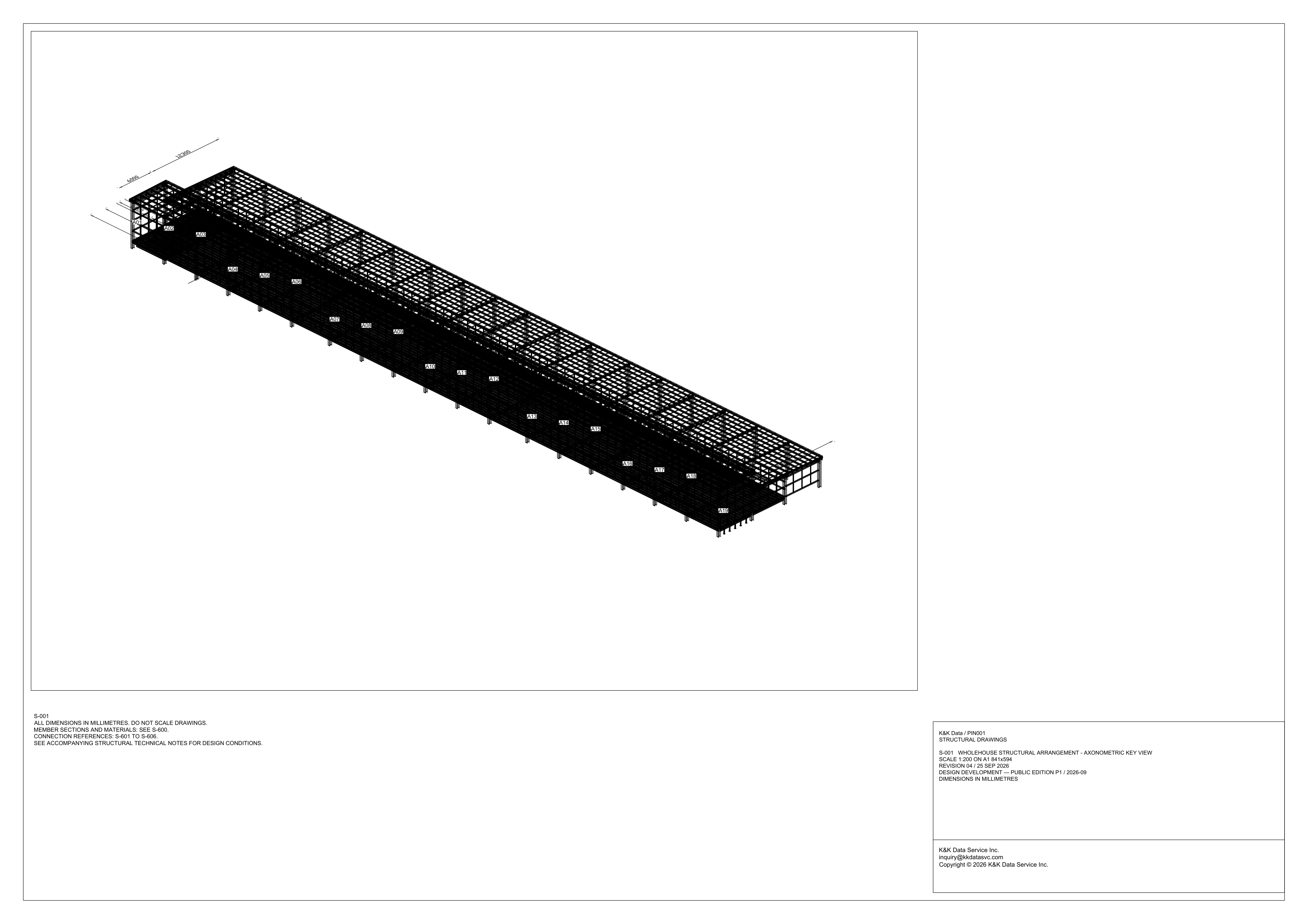
One axonometric key carries grids A01 to A19 and two roof-level schedules, every height given above the main column bases at model Z = 0.
Design Development — Public Edition P1: a reference design for study and evaluation, not a construction issue, not sealed by an Engineer of Record.
Scroll or pinch to zoom, drag to pan, click a highlighted device for its explanation. Vector drawing — it stays sharp at any magnification.
All structural sheets · S-100 →
What this sheet shows
S-001 is the whole-house structural arrangement, drawn as one axonometric key view at scale 1:200 on A1 (841x594). Grids A01 through A19 are labelled along the frame. On that view, two schedules each carry the heading ROOF LEVELS ON THIS SECTION (mm ABOVE DATUM). Every row is a Y station with a bearing level and a finished level, both in millimetres. Each schedule closes on the same datum sentence: the project vertical datum is the main column bases, model Z = 0, printed as Z = 0.000 mm. The first schedule lists Y=-338, Y=0, Y=6000, Y=6338 and Y=6260.82. The second repeats Y=6000, Y=6338 and Y=6260.82, then continues with Y=12000, Y=18300 and Y=18638. The grid bubbles do not restate those levels, and the title block does not either.
How the two level schedules fit together
Where both schedules name the same station, the figures match, so either block can be checked against the other without leaving the sheet. Y=6000 is bearing +7320.0 and finished +7421.6. Y=6338 is bearing +7326.8 and finished +7428.3. Y=6260.82 is bearing +4702.8 and finished +4804.3. That third station lies between Y=6000 and Y=6338, yet its bearing level is +4702.8 beside +7320.0 and +7326.8. The sheet is listing two levels across those Y stations, not one sequence that changes smoothly from row to row. At Y=-338, Y=0, Y=6000 and Y=6338, bearing runs +7193.3, +7200.0, +7320.0, +7326.8 and finished runs +7294.8, +7301.6, +7421.6, +7428.3, and each step in that list is an increase. At Y=6260.82, Y=12000, Y=18300 and Y=18638, bearing runs +4702.8, +4588.0, +4462.0, +4455.3 and finished runs +4804.3, +4689.6, +4563.6, +4556.8, and each step in that list is a decrease. Y=6338 still carries the higher pair even though its Y is greater than Y=6260.82. At every station the finished figure is the higher number on the row. The sheet does not state a build-up thickness in words; it prints the pair.
What the key view keeps, and what it sends elsewhere
The notes keep this drawing a key to the arrangement. All dimensions are in millimetres, and the sheet says not to scale the drawing, even though the title block gives 1:200 on A1. Member sections and materials are on S-600, not as labels on the axonometric. Connection references are S-601 to S-606. Design conditions are in the accompanying structural technical notes. A careful reader uses this sheet for the grid run and the two level schedules, and goes to those documents for a size, a joint or a design condition. The levels are stated here as millimetres above the main column bases. Section sizes and connection details are referenced outward rather than called out on the view. The same issue sits in the structural public edition, with the reference-design context under fire, structure and site.
Status
The title block reads K&K Data / PIN001, structural drawings, sheet S-001, revision 04 / 25 SEP 2026. The issue line is Design Development — Public Edition P1 / 2026-09, and dimensions are in millimetres. In that form the sheet is a reference design for study and evaluation. It does not record a completed building. It also does not fill in the items it has already sent to S-600, to S-601 to S-606, and to the accompanying structural technical notes.
Sheet guide — the devices on this drawing
A01 — near end of the grid
Grid A01 is the first label in the run drawn on the axonometric. The key view carries the frame from this end through A19. Member sections are not labelled on the view; the notes send those to S-600.
A10 — grids along the middle of the frame
The grid bubbles continue in series along the frame. A10 lies in that run between A01 and A19, with A09 to one side and A11 to the other. The key view is where that whole series reads as one arrangement.
A19 — far end of the grid
Grid A19 is the last label in the series that starts at A01. The sheet title names the drawing an axonometric key view of the whole-house structural arrangement, and this end is where that labelled run stops.
Roof framing — lattice on the key view
The axonometric shows the roof as a framed lattice running with grids A01 to A19. Heights on this view are the bearing and finished figures in the two schedules, not lengths scaled off the picture. The sheet says not to scale the drawing.
Main column bases — datum Z = 0
Both schedules name the project vertical datum as the main column bases, model Z = 0, printed Z = 0.000 mm. The roof levels on this sheet are millimetres above that datum. The axonometric brings the frame down to those bases. It does not call out a base detail on this view. Connection references for the set are S-601 to S-606.
Roof levels — two schedules above the datum
Two blocks headed ROOF LEVELS ON THIS SECTION give bearing and finished levels in millimetres above the main column bases (model Z = 0, Z = 0.000 mm). They agree at Y=6000 (+7320.0 / +7421.6), Y=6338 (+7326.8 / +7428.3) and Y=6260.82 (+4702.8 / +4804.3). The first block also lists Y=-338 and Y=0; the second continues through Y=12000, Y=18300 and Y=18638.
General notes — millimetres, S-600, S-601 to S-606
The note block states that all dimensions are in millimetres and that the drawings are not to be scaled. Member sections and materials are on S-600. Connection references are S-601 to S-606. Design conditions are in the accompanying structural technical notes, not written out on this key view.
Title block — S-001, revision 04
K&K Data / PIN001, structural drawings. The title is the whole-house structural arrangement, axonometric key view, sheet S-001. Scale 1:200 on A1, 841x594. Revision 04 / 25 SEP 2026, issued as Design Development — Public Edition P1 / 2026-09.
Get the full drawing set
This sheet is one page of the Structural Document Set — Public Edition P1 (170 pages, 84 MB) — a direct PDF download with a published SHA-256 checksum, no registration. The complete coordinated set is on the downloads page. Background guides: data center one-line diagrams · GB300 NVL72 facility requirements · liquid cooling and CDU design.
Questions about any device or parameter on this sheet: inquiry@kkdatasvc.com or the contact page.