
Data Center Lab · Reference Designs · Structural
Sheet S-100: Column, Base and Support Key Plan on Grids A01 to A19
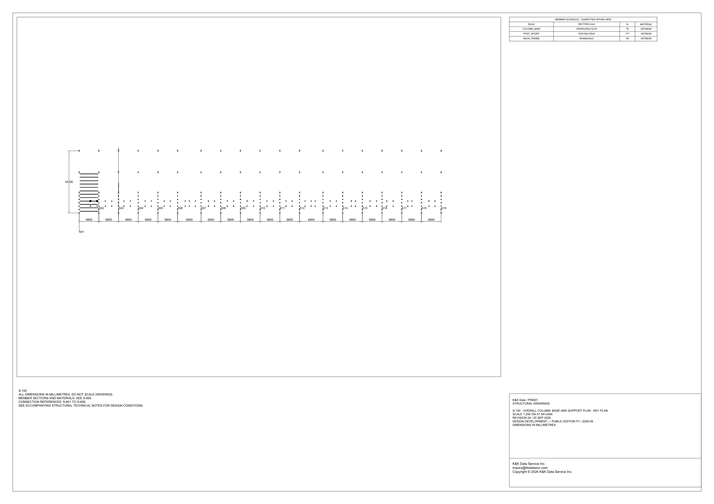
One key plan carries grids A01 to A19, the 5800 mm and 6900 mm bays, and the in-view count of main columns, short posts and rack frames.
Design Development — Public Edition P1: a reference design for study and evaluation, not a construction issue, not sealed by an Engineer of Record.
Scroll or pinch to zoom, drag to pan, click a highlighted device for its explanation. Vector drawing — it stays sharp at any magnification.
← S-001 · All structural sheets · S-501 →
What this sheet shows
S-100 is the overall column, base and support plan, drawn as one key plan. The title block gives the scale as 1:250 on A1, 841x594. Grids A01 through A19 are labelled along the plan, and a bay dimension is printed under each interval of that run. On the left, perpendicular to those grids, the sheet dimensions the column field as 18300 mm. It does not break that 18300 mm figure into smaller cross-dimensions on this sheet. The marks repeat across that depth. The drawing is the locator for where the lines of support sit. The count of what is in the view is the schedule at the upper right, headed MEMBER SCHEDULE - QUANTITIES WITHIN VIEW, with roles COLUMN_MAIN, POST_SHORT and RACK_FRAME. Role names are not repeated as tags along the grid.
Bay dimensions along the A grids
Along A01 to A19 the printed bay dimensions are 5800 mm, except at two intervals. The dimension between A06 and A07 reads 6900 mm, and the dimension between A12 and A13 reads 6900 mm. Those are the only 6900 mm figures on the chain. The bays from A01 to A06, from A07 to A12, and from A13 to A19 are printed 5800 mm. The sheet does not say why those two intervals are longer. A reader can see the break in the rhythm, and cannot take a reason for it from this drawing. The 18300 mm figure is the cross dimension drawn on the left of the plan, perpendicular to the grids. It is not printed as a bay between two A grids. The notes say ALL DIMENSIONS IN MILLIMETRES. DO NOT SCALE DRAWINGS, and they do not give a scale. The 5800 mm and 6900 mm figures are the dimensions, and the picture is not a substitute for them.
Quantities within the view
The schedule has four columns: ROLE, SECTION (mm), N and MATERIAL. COLUMN_MAIN is HW350x350x12x19, with N of 76 and material ASTMA36. POST_SHORT is SHS100x100x5, with N of 171 and material ASTMA36. RACK_FRAME is RHS80x40x3, with N of 66 and material ASTMA36. The material entry is the same string, ASTMA36, on every row. The heading limits the counts: MEMBER SCHEDULE - QUANTITIES WITHIN VIEW. The section strings identify the members in that view. The notes do not expand them into a specification; they send member sections and materials to S-600. A reader takes the role, the printed section and the in-view count from this table, and goes to S-600 for the section and material record the notes point to.
Status
The title block reads K&K Data / PIN001, structural drawings, sheet S-100, revision 04 / 25 SEP 2026. The issue line is Design Development — Public Edition P1 / 2026-09, and dimensions are in millimetres. In that form the sheet is a reference design for study and evaluation. It does not record a completed structure. The notes on the sheet are short, and they name where the rest of the structural information is carried. All dimensions are in millimetres, and the drawings are not to be scaled. Member sections and materials are on S-600. Connection references are S-601 to S-606. Design conditions are in the accompanying structural technical notes. This key plan gives the grids, the bay figures, the 18300 mm cross dimension and the in-view counts. A size beyond the printed section string, a joint, or a design condition is in those other documents. The reference-design context for the set is under fire, structure and site.
Sheet guide — the devices on this drawing
A01 — grid start and the 18300 mm cross dimension
Grid A01 is the first label on the key plan. The 18300 mm dimension is set out on the left, across the column field and perpendicular to the A grids, and this sheet does not split that figure into smaller cross-dimensions. The bay from A01 to A02 is printed 5800 mm. At this end the plan is drawn with a tighter group of lines than the marks farther along the grid, and that group is not given a role name on the plan.
A06–A07 — 6900 mm bay
The bay between A06 and A07 is dimensioned 6900 mm. From A01 to A06, and again from A07 to A12, the printed bays are 5800 mm. This is one of the two longer intervals on the chain. The drawing does not state why this bay differs from the 5800 mm bays beside it.
A12–A13 — 6900 mm bay
The second 6900 mm bay lies between A12 and A13. From A13 through A19 the chain returns to 5800 mm, and the same 5800 mm figure is what the sheet prints from A07 to A12. As with the A06–A07 bay, no note on this sheet explains the longer spacing.
A14–A19 — 5800 mm bays to the end of the grid
Grid A19 is the last label in the run that starts at A01. The closing bays, from A13 to A19, are printed 5800 mm. The key plan stops the labelled grid here. Member sections are not written on the grid bubbles. The schedule names the sections, and the notes send member sections and materials to S-600.
Column marks — A01 through the middle of the grid
The plan draws the column, base and support arrangement as marks across the 18300 mm dimension. The schedule is where the sheet names COLUMN_MAIN, POST_SHORT and RACK_FRAME and counts them within this view. Connection references for the set are S-601 to S-606, not callouts on the key plan.
Member schedule — quantities within view
COLUMN_MAIN is section HW350x350x12x19, count 76, material ASTMA36. POST_SHORT is SHS100x100x5, count 171, ASTMA36. RACK_FRAME is RHS80x40x3, count 66, ASTMA36. The heading says these are quantities within view. Member sections and materials beyond this identification are referred to S-600.
General notes — millimetres, S-600, S-601 to S-606
The note block states that all dimensions are in millimetres and that the drawings are not to be scaled. Member sections and materials: see S-600. Connection references: S-601 to S-606. Design conditions are in the accompanying structural technical notes, not written out on this key plan.
Title block — S-100, revision 04
K&K Data / PIN001, structural drawings. The title is the overall column, base and support plan, key plan, sheet S-100. Scale 1:250 on A1, 841x594. Revision 04 / 25 SEP 2026, issued as Design Development — Public Edition P1 / 2026-09. Dimensions in millimetres.
Get the full drawing set
This sheet is one page of the Structural Document Set — Public Edition P1 (170 pages, 84 MB) — a direct PDF download with a published SHA-256 checksum, no registration. The complete coordinated set is on the downloads page. Background guides: data center one-line diagrams · GB300 NVL72 facility requirements · liquid cooling and CDU design.
Questions about any device or parameter on this sheet: inquiry@kkdatasvc.com or the contact page.