
Data Center Lab · Reference Designs · Structural
Sheet S-501: Transverse Frame on Axis 3 — Roof Levels Above the Main Column Bases
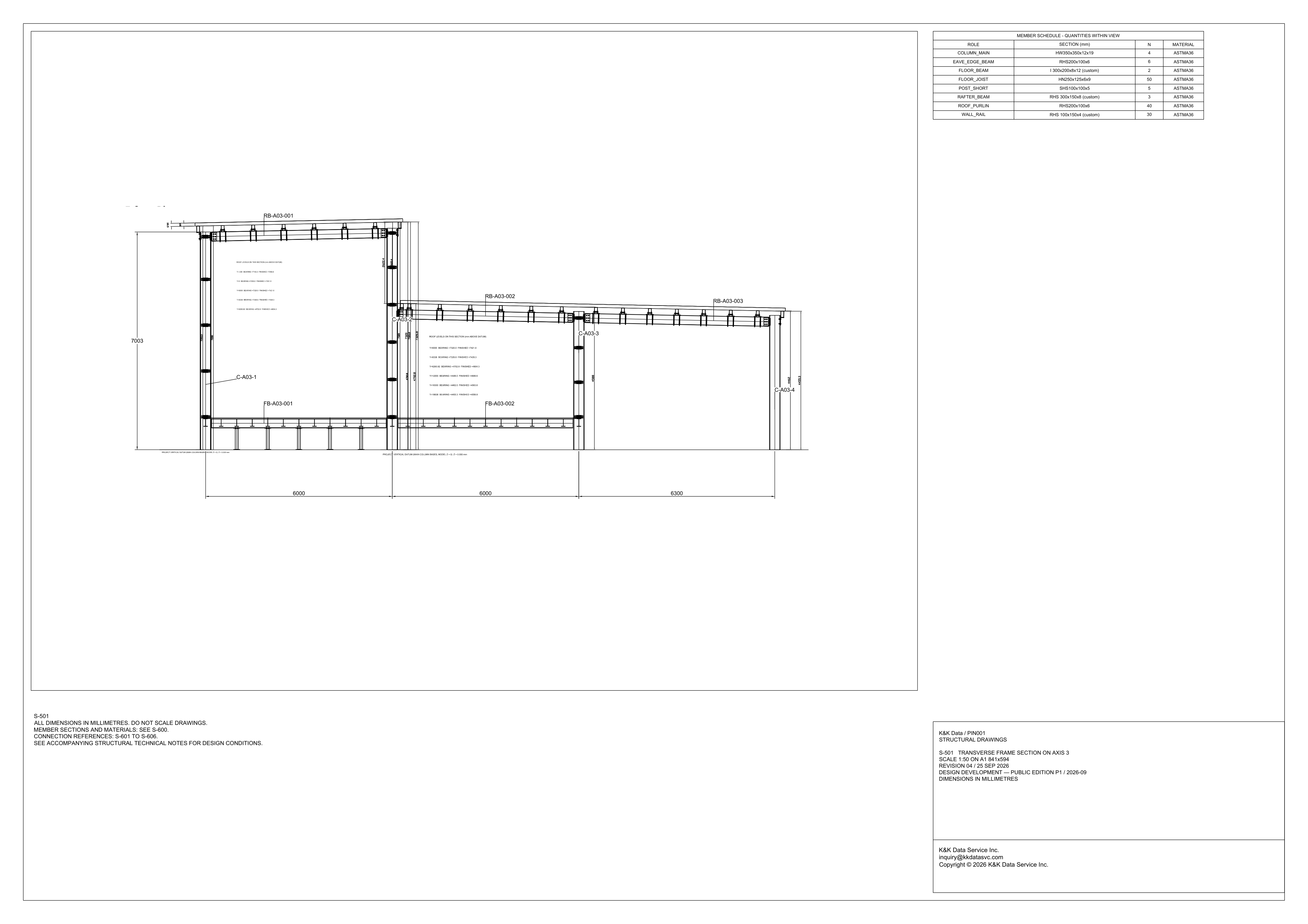
The axis 3 frame is where the roof step can be read in the drawing and in the levels: a 7003 mm bay, then lower bearing figures, all above the main column bases.
Design Development — Public Edition P1: a reference design for study and evaluation, not a construction issue, not sealed by an Engineer of Record.
Scroll or pinch to zoom, drag to pan, click a highlighted device for its explanation. Vector drawing — it stays sharp at any magnification.
← S-100 · All structural sheets · S-601 →
What this sheet shows
S-501 is the transverse frame section on axis 3. The title block gives the scale as 1:50 on A1, 841x594. Three horizontal dimensions are printed under the frame: 6000, then 6000, then 6300. The left-hand bay carries a vertical dimension of 7003, and the roof over that bay is drawn higher than the roof over the two bays to its right. The profile steps down at the column between the first bay and the second. The frame marks four main columns, C-A03-1, C-A03-2, C-A03-3 and C-A03-4; three rafters, RB-A03-001, RB-A03-002 and RB-A03-003; and two floor beams, FB-A03-001 and FB-A03-002. Purlins are drawn along the rafters and joists along the floor beams, without a separate mark on each piece. Axis 3 is named in the sheet title, and the column, rafter and floor-beam marks carry A03. The 7003 dimension is printed on the high bay, and that figure is not one of the bearing or finished levels. Counts for every role are in the schedule headed MEMBER SCHEDULE - QUANTITIES WITHIN VIEW.
Roof levels on this section
Two blocks on the section are each headed ROOF LEVELS ON THIS SECTION (mm ABOVE DATUM). Every row is a Y station with a bearing level and a finished level, both in millimetres. Each block closes on the same datum sentence: the project vertical datum is the main column bases, model Z = 0, printed as Z = 0.000 mm. One block lists five stations. Y=-338 is bearing +7193.3 and finished +7294.8. Y=0 is bearing +7200.0 and finished +7301.6. Y=6000 is bearing +7320.0 and finished +7421.6. Y=6338 is bearing +7326.8 and finished +7428.3. Y=6260.82 is bearing +4702.8 and finished +4804.3. The other block repeats Y=6000, Y=6338 and Y=6260.82 with those same pairs, then continues. Y=12000 is bearing +4588.0 and finished +4689.6. Y=18300 is bearing +4462.0 and finished +4563.6. Y=18638 is bearing +4455.3 and finished +4556.8. Where both blocks name the same station, the figures match. On every row the finished figure is the higher number. The sheet does not state a build-up thickness in words; it prints the pair. From Y=-338 to Y=0 to Y=6000 to Y=6338 the bearing figures are +7193.3, +7200.0, +7320.0 and +7326.8. Y=6260.82 lies between Y=6000 and Y=6338, and its bearing is +4702.8. The other block then gives +4588.0 at Y=12000, +4462.0 at Y=18300 and +4455.3 at Y=18638. The drawing shows the same split: a high roof over the first bay and a lower roof from the step onward. The vertical frame dimension 7003 is not any of these bearing or finished figures. Set beside the level stations, the bay dimensions 6000, 6000 and 6300 are the steps from Y=0 to Y=6000, from Y=6000 to Y=12000, and from Y=12000 to Y=18300.
Quantities within the view
The schedule has four columns: ROLE, SECTION (mm), N and MATERIAL. The material entry is ASTMA36 on every row. COLUMN_MAIN is HW350x350x12x19, with N of 4. RAFTER_BEAM is RHS 300x150x8 (custom), with N of 3. FLOOR_BEAM is I 300x200x8x12 (custom), with N of 2. Those three counts match the marks on the frame: four columns, three rafters and two floor beams. The other rows are counts within the view, and the sheet does not list an individual mark for each of those pieces. EAVE_EDGE_BEAM is RHS200x100x6, with N of 6. FLOOR_JOIST is HN250x125x6x9, with N of 50. POST_SHORT is SHS100x100x5, with N of 5. ROOF_PURLIN is RHS200x100x6, with N of 40. WALL_RAIL is RHS 100x150x4 (custom), with N of 30. The heading limits every figure to quantities within this view. Three of the section strings are printed with the word custom: the floor beam, the rafter and the wall rail. The notes do not expand the strings. They say member sections and materials: see S-600. The short-post count is 5 and the main-column count is 4, and the sheet does not explain the difference. Joists are counted as 50, against two floor beams, and purlins as 40, against three rafters. No spacing is printed on this section that would turn those counts into a pitch.
Status
The title block reads K&K Data / PIN001, structural drawings, sheet S-501, transverse frame section on axis 3. Scale 1:50 on A1, 841x594. Revision 04 / 25 SEP 2026. The issue line is Design Development — Public Edition P1 / 2026-09, and dimensions are in millimetres. In that form the sheet is a reference design for study and evaluation. It does not record a completed frame. The notes say that all dimensions are in millimetres and that the drawings are not to be scaled, even though the title block states a scale. Member sections and materials: see S-600. Connection references: S-601 to S-606. Design conditions are in the accompanying structural technical notes. This section gives the frame, the two level schedules and the in-view counts. A section size beyond the printed string, a joint, or a design condition is in those other documents. The sheet does not state a thickness between the bearing level and the finished level. The same issue sits in the structural public edition, with the reference-design context under fire, structure and site.
Sheet guide — the devices on this drawing
C-A03-1 — main column of the high bay
The left column of the high bay is marked C-A03-1. The vertical dimension beside it reads 7003. The schedule names COLUMN_MAIN as HW350x350x12x19 and counts 4 in this view, the four marks C-A03-1 to C-A03-4.
RB-A03-001 — rafter over the high bay
RB-A03-001 is the rafter mark on the high roof, over the bay dimensioned 6000. The schedule names RAFTER_BEAM as RHS 300x150x8 (custom) and counts 3 in this view, one mark for each rafter on the section. The members drawn along the rafter are the purlins, which the schedule counts as ROOF_PURLIN, RHS200x100x6, N of 40.
Roof levels — two blocks above the datum
Two blocks headed ROOF LEVELS ON THIS SECTION sit inside the frame. Stations run from Y=-338 to Y=18638, and where a station is listed twice the bearing and finished figures match, including Y=6000 at +7320.0 / +7421.6 and Y=6260.82 at +4702.8 / +4804.3. Each block ends on the main column bases, model Z = 0, printed Z = 0.000 mm, and the +4702.8 row is the one that sits with the lower roof rather than with +7326.8 at Y=6338.
C-A03-2 — column at the roof step
C-A03-2 is the column drawn at the roof step, between rafters RB-A03-001 and RB-A03-002. It is the second of the four COLUMN_MAIN marks, section HW350x350x12x19. The bearing and finished heights on either side of the step are the figures in the two level blocks.
FB-A03-001 — floor beam in the left bay
FB-A03-001 is the floor-beam mark in the left bay, the bay dimensioned 6000 beneath it, with joists drawn along the beam. The schedule names FLOOR_BEAM as I 300x200x8x12 (custom), two in the view, and FLOOR_JOIST as HN250x125x6x9, 50 in the view. The levels printed on this section are roof levels; no separate floor level is given.
RB-A03-002 and FB-A03-002 — middle bay
The middle bay is dimensioned 6000. Its rafter mark is RB-A03-002 and its floor-beam mark is FB-A03-002, the second of the two floor beams in the schedule. The roof here is the lower one, and column C-A03-3 at the right end of this bay is where the 6300 dimension begins.
RB-A03-003 — rafter over the 6300 mm bay
The right-hand bay is dimensioned 6300, from column C-A03-3 to column C-A03-4. The rafter mark over it is RB-A03-003, the third RAFTER_BEAM, section RHS 300x150x8 (custom). The sheet marks no third floor beam here; the floor-beam marks are FB-A03-001 and FB-A03-002, and the schedule count for FLOOR_BEAM is 2.
Member schedule — quantities within view
The schedule lists eight roles, all ASTMA36, as quantities within this view: COLUMN_MAIN HW350x350x12x19, N of 4; EAVE_EDGE_BEAM RHS200x100x6, N of 6; FLOOR_BEAM I 300x200x8x12 (custom), N of 2; FLOOR_JOIST HN250x125x6x9, N of 50; POST_SHORT SHS100x100x5, N of 5; RAFTER_BEAM RHS 300x150x8 (custom), N of 3; ROOF_PURLIN RHS200x100x6, N of 40; WALL_RAIL RHS 100x150x4 (custom), N of 30. The notes send member sections and materials to S-600 rather than specifying them here.
General notes — millimetres, S-600, S-601 to S-606
The note block states that all dimensions are in millimetres and that the drawings are not to be scaled. Member sections and materials are on S-600, and connection references are S-601 to S-606. Design conditions are in the accompanying structural technical notes, not written out on this section.
Title block — S-501, revision 04
K&K Data / PIN001, structural drawings. The title is the transverse frame section on axis 3, sheet S-501, at scale 1:50 on A1, 841x594. Revision 04 / 25 SEP 2026, issued as Design Development — Public Edition P1 / 2026-09, with dimensions in millimetres.
Get the full drawing set
This sheet is one page of the Structural Document Set — Public Edition P1 (170 pages, 84 MB) — a direct PDF download with a published SHA-256 checksum, no registration. The complete coordinated set is on the downloads page. Background guides: data center one-line diagrams · GB300 NVL72 facility requirements · liquid cooling and CDU design.
Questions about any device or parameter on this sheet: inquiry@kkdatasvc.com or the contact page.