
Data Center Lab · Reference Designs · Structural
Sheet S-601: How the RHS Beam Meets the HW Column — Cleats, Sleeves and Two Bolt Lengths
One joint at 1:5 is the beam meeting the column: two JSEC-01 cleats, six JSEC-02 sleeves, and M16 bolts of length 55 on the cleats and length 200 through the sleeves.
Design Development — Public Edition P1: a reference design for study and evaluation, not a construction issue, not sealed by an Engineer of Record.
Scroll or pinch to zoom, drag to pan, click a highlighted device for its explanation. Vector drawing — it stays sharp at any magnification.
← S-501 · All structural sheets
What this sheet shows
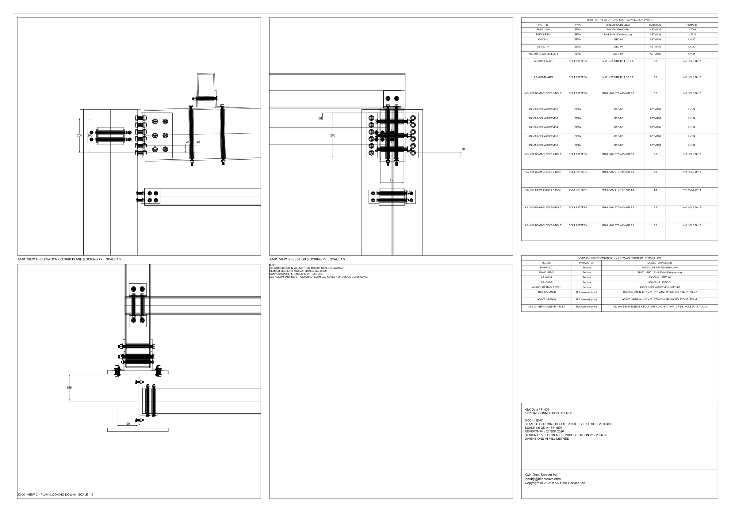
S-601 is typical connection JD-01. The title block names it in full: BEAM TO COLUMN - DOUBLE ANGLE CLEAT, SLEEVED BOLT, at scale 1:5 on A1, 841x594. Revision 04 is dated 25 SEP 2026, and the issue line is Design Development — Public Edition P1 / 2026-09. Three views, each marked scale 1:5, draw that one joint. View A is the elevation on the grid plane, looking +X. View B is the section, looking +Y. View C is the plan, looking down. The right side of the sheet schedules the joint. CONNECTION PARAMETERS - JD-01 (VALUE / MEMBER / PARAMETER) names column PIN001-C01, section HW350x350x12x19, and beam PIN001-RB01, section RHS 300x150x8 (custom). It names cleats ASJ-001-L and ASJ-001-R, both section JSEC-01, and sleeve ASJ-001-BEAM-SLEEVE-1, section JSEC-02. The bill headed BOM - DETAIL JD-01 - ONE JOINT, CONNECTION PARTS carries the sleeves on through ASJ-001-BEAM-SLEEVE-6. Under view B the notes say that dimensions are in millimetres, that the drawing is not to be scaled, that member sections and materials are on S-600, that connection references run from S-601 to S-606, and that design conditions are in the accompanying structural technical notes.
One joint and two bolt lengths
The bill is one joint. Its type column is a model label: PIN001-C01, PIN001-RB01, both cleats and all six sleeves are typed BEAM, and the fastener rows are typed BOLT PATTERN. Steel rows are material ASTMA36. Bolt rows are 8.8. Remarks give the modelled lengths: column L=7003, beam L=5611, each cleat L=260, each sleeve L=134. The column and beam lengths are member lengths in the bill. The 1:5 views draw the joint, and 260 and 134 are the lengths that also appear as dimensions on view B. The fasteners split by part ID. ASJ-001-L-MAIN and ASJ-001-R-MAIN are each M16 x 55, STD 4014, GR 8.8, remarked N=6 and hole diameter 18. The six sleeve-bolt rows, ASJ-001-BEAM-SLEEVE-1-BOLT through ASJ-001-BEAM-SLEEVE-6-BOLT, are each M16 x 200, STD 4014, GR 8.8, remarked N=1 and hole diameter 18. On the parameter rows the name is Bolt diameter (mm), and the cell is that full callout, including length, standard, grade, hole and tolerance. The parameters add TOL=2 and they name sleeve 1 only. The bill is where sleeves 2 to 6, and their bolts, each appear at the same size. The beam is an RHS, the title calls the joint a sleeved bolt, and the bolt tied to each sleeve is the 200 length. The cleat bolts are the 55 length. The sleeve callout is longer than the sleeve: 200 against a modelled sleeve of 134. The one-joint bill has no weld row, and neither table prints a resistance.
Dimensions on the three views
View A, the elevation looking +X, prints 200, 200, 40 and 40. The two 200 figures sit on the end detail at the left of that elevation, one vertical and one horizontal. The two 40 figures are horizontal dimensions at the column side of the same view. View B, the section looking +Y, prints 260, 134, 53 and two figures of 30. The 260 dimension runs vertically across the cleat, and the bill gives each JSEC-01 cleat the modelled length 260. The 134 dimension runs along the sleeve, and the bill gives each JSEC-02 sleeve the modelled length 134. A small end view under that section is dimensioned 53. One 30 is printed at the top of the joint and the other at the right-hand side. View C, the plan looking down, prints 156 vertically across the beam depth and 120 horizontally under the column. Those plan figures stand on their own: the member section marks on this sheet are HW350x350x12x19 and RHS 300x150x8 (custom). Cleat and sleeve stay at the codes JSEC-01 and JSEC-02, which this sheet does not draw out into leg sizes. Member sections and materials are the S-600 reference. Design conditions are the reference to the accompanying structural technical notes. The connection-reference note places this sheet in the run S-601 to S-606.
Status
The title block reads K&K Data / PIN001, typical connection details, sheet S-601 / JD-01. Revision 04 / 25 SEP 2026. The issue line is Design Development — Public Edition P1 / 2026-09, and the block repeats that dimensions are in millimetres. In that form the sheet is a reference design for study and evaluation. It does not record a completed connection. It records the joint in three views at 1:5, the part marks, the two bolt callouts, hole diameter 18 with tolerance 2, and the modelled lengths in the one-joint bill. The cleat and the sleeve remain JSEC-01 and JSEC-02 on this page, and no resistance figure is printed. Those are the outward references already set under view B: member sections and materials on S-600, the connection series S-601 to S-606, and the accompanying structural technical notes. The same issue sits in the structural public edition, with the reference-design context under fire, structure and site.
Sheet guide — the devices on this drawing
PIN001-C01 — column at joint JD-01
View A draws the column as the vertical member of the elevation, looking +X. The parameters and the bill give it section HW350x350x12x19, material ASTMA36, and the bill remark is L=7003. In that bill the type word on this row is BEAM, the same type word used for the beam, the cleats and the sleeves.
PIN001-RB01 — beam at joint JD-01
The beam meets the column in view A and is sectioned in view B, looking +Y. Its section is RHS 300x150x8 (custom), material ASTMA36, and the bill remark is L=5611. The joint title calls the connection a sleeved bolt, and the sleeve parts are named on this beam.
ASJ-001-L and ASJ-001-R — double angle cleats
The two cleats are the double angle of the title, marked L and R. Both are section JSEC-01, material ASTMA36, modelled length 260. View B prints 260 vertically across the cleat. This sheet leaves JSEC-01 as a code; the notes send member sections and materials to S-600.
ASJ-001-BEAM-SLEEVE-1 to 6 — beam sleeves
The bill lists six sleeves, ASJ-001-BEAM-SLEEVE-1 through ASJ-001-BEAM-SLEEVE-6, each section JSEC-02, material ASTMA36, modelled length 134. View B prints 134 along the sleeve and 53 on the small end view under the section. The parameters name sleeve 1; the six rows are in the bill.
Cleat bolts and sleeve bolts — two M16 lengths
ASJ-001-L-MAIN and ASJ-001-R-MAIN are each M16 x 55, STD 4014, GR 8.8, remarked N=6, hole diameter 18. Each sleeve bolt, ASJ-001-BEAM-SLEEVE-1-BOLT through ASJ-001-BEAM-SLEEVE-6-BOLT, is M16 x 200, remarked N=1, with the same hole. The parameters add TOL=2.
View C — plan dimensions 156 and 120
View C is the plan, looking down, at scale 1:5. It prints 156 vertically across the beam depth and 120 horizontally under the column. The member section marks on this sheet are HW350x350x12x19 and RHS 300x150x8 (custom), so the plan dimensions are read here and the member sizes are read from those marks.
BOM — one joint, connection parts
The bill is headed BOM - DETAIL JD-01 - ONE JOINT, CONNECTION PARTS. The rows are the column, the beam, two JSEC-01 cleats, six JSEC-02 sleeves, two cleat bolt patterns and six sleeve-bolt patterns. Modelled lengths sit in the remark column. No weld row is printed in this bill.
Connection parameters — callout and tolerance
The block repeats the column, the beam, both cleats, sleeve 1, both cleat bolt patterns and sleeve-bolt 1. The bolt rows are named Bolt diameter (mm), and the model-parameter cell is the full callout, M16 x 55 or M16 x 200, with STD 4014, GR 8.8, HOLE D=18 and TOL=2. Sleeves 2 to 6 stay in the bill.
Notes under view B — reading rules
The notes under the section say that all dimensions are in millimetres and that the drawing is not to be scaled, beside views marked 1:5. Member sections and materials: see S-600. Connection references: S-601 to S-606. Design conditions are in the accompanying structural technical notes.
Get the full drawing set
This sheet is one page of the Structural Document Set — Public Edition P1 (170 pages, 84 MB) — a direct PDF download with a published SHA-256 checksum, no registration. The complete coordinated set is on the downloads page. Background guides: data center one-line diagrams · GB300 NVL72 facility requirements · liquid cooling and CDU design.
Questions about any device or parameter on this sheet: inquiry@kkdatasvc.com or the contact page.