
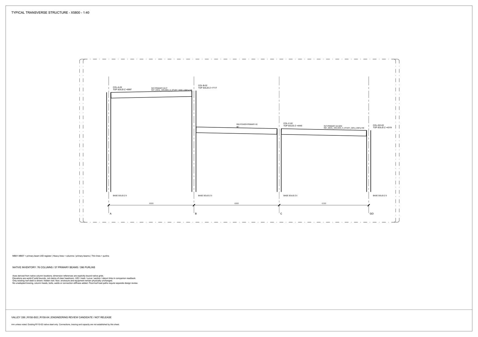
Battery-room area on this plant spans twenty-seven times; the mass span is unquantified and necessarily greater [MODELED]. The seismic value sits in equipment and its attachment to the slab: transformers, uninterruptible supply modules, battery racks, generator sets and flooded pipework. On that basis the structural chapter ranks the two risks against each other and puts the frame second. Failure of the main frame is not the governing seismic risk here; failure of nonstructural component anchorage is. The load table that would let anyone size that anchorage is blocked by three chains at once [TARGET], and none of the three belongs to the structural discipline.
Seismic Category, Anchorage Code, and Supplier Data Are Blocked
The anchorage verification class has every input in a blocked state, and the blockers do not share a route to closure:
- the seismic design category, which needs both a code adoption decision and a site class from a geotechnical investigation;
- adoption of the anchorage provisions themselves, which fixes the interaction expression and the cracked-concrete assumption;
- supplier data at drawing grade, which alone can give the centre of gravity and the support point coordinates that an overturning calculation requires.
All three have to close before the class advances, which makes it the most heavily blocked class in the chapter.
The slab and the anchors are also locked to each other in both directions. Slab thickness limits effective embedment, which limits single-anchor capacity, which limits the equipment seismic force that can be anchored at all. Running the other way, the equipment seismic force sets a required embedment, which sets a minimum thickness or a local thickening or a separate equipment foundation. The chapter judges the second direction likely to govern on this project and does not demonstrate it, then draws the procedural consequence anyway: the slab-type branch and the anchor branch are one iteration, and sizing the slab from the floor load classes and checking anchorage afterwards is the wrong order.
Typical cabinet feet still lose a uniform-load check to punching. A single plant-wide kilonewton-per-square-metre figure is unverifiable without a failure mode, a loaded area, a room and a branch. The white-floor target does not cover the battery room.
Delegated Anchorage Assumes an Unreviewed Seismic Force
The basis records that anchorage design is often passed down to the contractor as delegated design, and its six-link responsibility chain shows what that presumes [TARGET]. The record engineer determines the component seismic and wind forces. The supplier gives support points and permitted attachment methods, an anchor calculation follows, and the base material geometry and reinforcement are made to suit. The post-installed product is then qualified along with its installer, and a special inspection after installation closes the chain with the authority. Link one is the blocked one. Delegating link three while link one is open forces the contractor to assume the force, and that assumption is reviewed by nobody.
A second default is being set at the same time. Cast-in anchors need supplier support coordinates before the pour, those coordinates are empty for every item in the equipment register, and so the project is being pushed toward post-installed anchorage by an absence of information and not by a decision anyone made or recorded. The basis declines to log that as a selection and logs it as a schedule risk instead, asking that the date the drawing-grade support coordinates arrive be paired with the pour date as an explicit programme constraint.
The component importance factor is the single ruling that would narrow the argument. If the factor is ruled not to require post-earthquake function, the seismic bracing of the flooded cooling pipework becomes a compliance detail again, and the observation that a single seismic event can remove the supports of all three nominally independent cooling zones [MODELED] stops being an availability argument. No such ruling has been made and the factor is undetermined, so neither reading is settled. The anchorage would still govern; it would no longer carry the cooling redundancy claim.
A Shared Hanger Can Remove Supports of All Three Cooling Zones
Bracing is not contained within one discipline either. A shared hanger carrying pipework and tray on one frame would cross the space model's exclusion band, which keeps power and fibre tray out of a vertical column 0.30 m either side of the liquid pipe projection [TARGET]. Support positions also set where the bonding jumpers across insulating joints and hose sections have to go, and that object list is empty because pipe materials are undecided. The hanging-load register is not sufficient to carry a steel tonnage either: no system in it has a value, so structural dead load exists only as a variable.
The grounding system is the one system that must connect the plant, so a seismic failure of hangers and a seismic failure of earth conductors through compartment walls are two common-cause paths, not one. Neither currently has an owner.
The responsibility table in the same chapter puts execution and approval of anchorage and equipment-foundation design on the licensed structural engineer of record, with the supplier answerable for the stamped support reactions that feed it. That table is written as a recommendation and registered as awaiting owner contract confirmation, so the party who would issue the force table is proposed and not yet appointed.
Limits and open items
Confirmed: failure of the main frame is not the governing seismic risk on this plant; failure of nonstructural component anchorage is. [FACT]
The twenty-seven-times battery-room area span and the three-zone hanger common cause remain study observations [MODELED]. The three blocked input chains, the six-link delegated chain and the 0.30 m exclusion band remain register and geometry figures [TARGET].
Open: seismic design category; site class; anchorage provisions; drawing-grade support coordinates; the component importance factor; pipe materials and jumper positions. No structural analysis was performed. Nothing here has been sealed. Nothing releases an anchor quantity. [HOLD]
Pair the arrival of drawing-grade support coordinates with the pour date. Until that pair exists, the project is selecting post-installed anchorage by calendar, not by calculation.
© 2026 K&K Data Service Inc. All rights reserved. Reproduction or republication is permitted only with clear attribution to K&K Data Service Inc. and a working hyperlink to the canonical URL of this article. Excerpts must preserve the technical context, maturity labels, assumptions, and limitations. No excerpt may imply project approval, field validation, certification, or endorsement that the original article does not state.
Source: K&K Data Service Inc., “Nonstructural Anchorage, Not the Frame, Is the Seismic Risk,” https://www.kkdatasvc.com/lab/fire-structure-site-and-compliance/nonstructural-anchorage-not-the-frame-is-the-seismic-risk/.
Discuss This Constraint. If your project record shows a different result, or the same failure domain under another name, we want to see it. Email inquiry@kkdatasvc.com or use the contact page.