
Data Center Lab · Reference Designs · Network
Sheet N-302-EN: Which tray lands the trunks on the CVS and SPA/SPB cabinets, and how the fan-wall front zone is shared
The trunk table gives every SPA cabinet 120 trunks on TA and every SPB cabinet 120 on TB, every CVS cabinet 60, and note 4 states that the 1,050 mm fan-wall front zone is shared in time.
Design Development — Public Edition P1: a reference design for study and evaluation, not a construction issue, not sealed by an Engineer of Record.
Scroll or pinch to zoom, drag to pan, click a highlighted device for its explanation. Vector drawing — it stays sharp at any magnification.
← N-301-EN · All network sheets · N-303-EN →
What this sheet shows
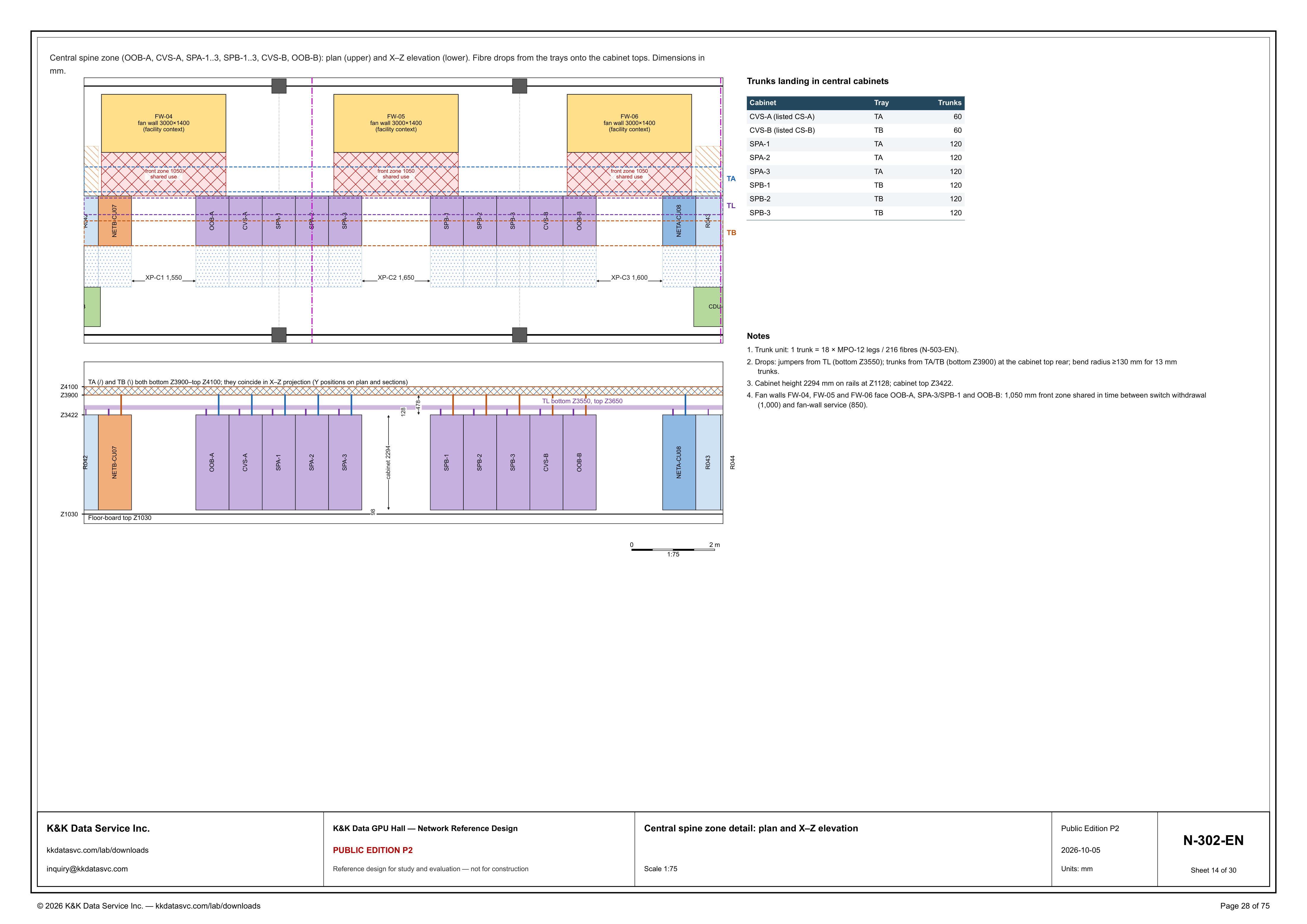
N-302-EN is the central-spine detail, drawn at 1:75. The line under the top border names the zone and the two views: Central spine zone (OOB-A, CVS-A, SPA-1..3, SPB-1..3, CVS-B, OOB-B): plan (upper) and X–Z elevation (lower). Fibre drops from the trays onto the cabinet tops. Dimensions in mm. The plan puts fan walls FW-04, FW-05 and FW-06 along the upper side, each marked fan wall 3000×1400 and (facility context), with a hatched front zone 1050 shared use in front of each. Under the walls the cabinet row is R042, NETB-CU07, OOB-A, CVS-A, SPA-1, SPA-2 and SPA-3, then a gap, then SPB-1, SPB-2, SPB-3, CVS-B, OOB-B, NETA-CU08 and R043. Dashed lines are labeled TA on the fan-wall side of the cabinets, TL along the row and TB on the side with the dotted band. The lower view is the X–Z elevation of the same run, and that view labels R044 past R043. The graphic scale under the elevation reads 0 to 2 m and is marked 1:75. The detail is part of the GPU hall reference.
Trunks landing in the central cabinets
The table at the upper right is titled Trunks landing in central cabinets, with columns Cabinet, Tray and Trunks. CVS-A (listed CS-A) is on TA with 60 trunks, and CVS-B (listed CS-B) is on TB with 60 trunks. SPA-1, SPA-2 and SPA-3 are each on TA with 120 trunks. SPB-1, SPB-2 and SPB-3 are each on TB with 120 trunks. On the plan, TA is the dashed line on the fan-wall side of the row and TB is the dashed line on the side with the dotted band, so the CVS-A and SPA rows use the fan-wall-side tray and the CVS-B and SPB rows use the far-side tray. The header's zone is OOB-A, CVS-A, SPA-1..3, SPB-1..3, CVS-B, OOB-B. OOB-A and OOB-B are on that list and on the plan, and neither is a row in this table. Note 1 fixes the unit behind every count in the table: 1 trunk = 18 × MPO-12 legs / 216 fibres, and it points that definition to N-503-EN.
Drops, elevations and the shared front zone
Note 2 separates the two drops onto the cabinet top. Jumpers come from TL, bottom Z3550. Trunks come from TA/TB, bottom Z3900, and enter at the cabinet top rear. Bend radius is at least 130 mm for 13 mm trunks. The elevation draws TA and TB as one band because the caption says TA (/) and TB (\) both run bottom Z3900–top Z4100 and coincide in X–Z projection, with Y positions on the plan and on the sections. TL is the lower band, labeled bottom Z3550, top Z3650. The elevation dimensions 128 from the cabinet-top line Z3422 up to the TL bottom, and 478 from that line up to the TA/TB bottom at Z3900. Note 3 gives the cabinet: height 2294 mm on rails at Z1128, cabinet top Z3422. The elevation dimensions 98 from floor-board top Z1030 up to the cabinet base and labels the body cabinet 2294. The printed figures meet: Z1030 plus 98 is Z1128, and Z1128 plus 2294 is Z3422. Z3422 plus 128 is the TL bottom Z3550, and Z3422 plus 478 is the TA/TB bottom Z3900. Note 4 names the front zone. Fan walls FW-04, FW-05 and FW-06 face OOB-A, SPA-3/SPB-1 and OOB-B. The note gives a 1,050 mm front zone shared in time between switch withdrawal (1,000) and fan-wall service (850). The plan prints that zone on each wall as front zone 1050 shared use.
Status
The title block dates the sheet 2026-10-05 and issues it as Public Edition P2, number N-302-EN, sheet 14 of 30, scale 1:75, units mm. The sheet title is Central spine zone detail: plan and X–Z elevation. The status line reads: reference design for study and evaluation — not for construction. Note 1 points the trunk unit, 18 × MPO-12 legs / 216 fibres, to N-503-EN. Notes 2 and 3 state the drop elevations and the 2294 mm cabinet on rails at Z1128, with cabinet top Z3422. Note 4 states the 1,050 mm front zone shared in time between switch withdrawal (1,000) and fan-wall service (850). The drawing is part of the Public Edition P2 network reference design.
Sheet guide — the devices on this drawing
Central spine zone — plan upper, X–Z elevation lower
The line under the border names the subject: Central spine zone (OOB-A, CVS-A, SPA-1..3, SPB-1..3, CVS-B, OOB-B): plan (upper) and X–Z elevation (lower). Fibre drops from the trays onto the cabinet tops. Dimensions in mm. The upper drawing is the plan and the lower drawing is the elevation.
FW-04, FW-05, FW-06 — fan walls 3000×1400
FW-04, FW-05 and FW-06 are the three blocks along the upper side of the plan. Each is marked fan wall 3000×1400 and (facility context). Note 4 says these walls face OOB-A, SPA-3/SPB-1 and OOB-B. FW-04 is the left wall, FW-05 the middle wall and FW-06 the right wall.
Front zone 1050 — shared use at the three fan walls
A hatched band in front of each fan wall is labeled front zone 1050 shared use. Note 4 calls the same band a 1,050 mm front zone shared in time between switch withdrawal (1,000) and fan-wall service (850). The plan prints that label on the band at FW-04, at FW-05 and at FW-06.
R042 through SPA-3 — NETB-CU07, OOB-A, CVS-A
The left of the plan row is R042, NETB-CU07, OOB-A, CVS-A, SPA-1, SPA-2 and SPA-3. The trunk table puts CVS-A (listed CS-A) on TA with 60 trunks, and SPA-1, SPA-2 and SPA-3 each on TA with 120 trunks. TA is the dashed line on this fan-wall side of the row. OOB-A is named in the zone header and has no trunk row.
SPB-1 through R043 — CVS-B, OOB-B, NETA-CU08
After the gap the plan row continues SPB-1, SPB-2, SPB-3, CVS-B, OOB-B, NETA-CU08 and R043. The trunk table puts SPB-1, SPB-2 and SPB-3 each on TB with 120 trunks, and CVS-B (listed CS-B) on TB with 60 trunks. TB is the dashed line on the dotted-band side of the row. OOB-B is named in the zone header and has no trunk row.
XP-C1 1,550, XP-C2 1,650, XP-C3 1,600
The dotted band on the TB side of the cabinet row prints three dimensions. XP-C1 1,550 is the left one, XP-C2 1,650 is the middle one at the gap between SPA-3 and SPB-1, and XP-C3 1,600 is the right one. The sheet prints those three strings on this band.
Trunk table — CVS 60, SPA and SPB 120
Trunks landing in central cabinets. CVS-A (listed CS-A) is tray TA, 60 trunks. CVS-B (listed CS-B) is tray TB, 60 trunks. SPA-1, SPA-2 and SPA-3 are each tray TA, 120 trunks. SPB-1, SPB-2 and SPB-3 are each tray TB, 120 trunks. Note 1 sets the unit at 1 trunk = 18 × MPO-12 legs / 216 fibres (N-503-EN).
Notes 1–4 — trunk unit, drops, height, front zone
Note 1 defines 1 trunk as 18 × MPO-12 legs / 216 fibres and cites N-503-EN. Note 2 sends jumpers from TL at bottom Z3550, and trunks from TA/TB at bottom Z3900 into the cabinet top rear, with bend radius at least 130 mm for 13 mm trunks. Note 3 is cabinet height 2294 mm on rails at Z1128, cabinet top Z3422. Note 4 is the 1,050 mm front zone shared in time between switch withdrawal (1,000) and fan-wall service (850).
X–Z elevation — tray drops, 2294 mm cabinets, through R044
TA (/) and TB (\) both run bottom Z3900–top Z4100 and coincide in this view, with Y positions on the plan and on the sections. TL is bottom Z3550, top Z3650. The view dimensions 128 from cabinet top Z3422 up to the TL bottom and 478 from Z3422 up to the TA/TB bottom. The row is R042, NETB-CU07, OOB-A, CVS-A, SPA-1, SPA-2, SPA-3, then the gap, then SPB-1, SPB-2, SPB-3, CVS-B, OOB-B, NETA-CU08, R043 and R044. The body is cabinet 2294, and 98 runs from floor-board top Z1030 to the base. Z1030 plus 98 is Z1128, Z1128 plus 2294 is Z3422, Z3422 plus 128 is Z3550, and Z3422 plus 478 is Z3900.
N-302-EN — title block, sheet 14 of 30
The title block names the sheet Central spine zone detail: plan and X–Z elevation, at scale 1:75, units mm, number N-302-EN, sheet 14 of 30. The edition cell reads Public Edition P2, dated 2026-10-05. The status line reads: reference design for study and evaluation — not for construction.
Get the full drawing set
This sheet is one page of the GPU Hall Network Reference Design — Public Edition P2 (75 pages, 1.6 MB) — a direct PDF download with a published SHA-256 checksum, no registration. The complete coordinated set is on the downloads page. Background guides: data center one-line diagrams · GB300 NVL72 facility requirements · liquid cooling and CDU design.
Questions about any device or parameter on this sheet: inquiry@kkdatasvc.com or the contact page.