
Data Center Lab · Reference Designs · Network
Sheet N-303-EN: Calculated MMS4X00-NS uplinks from far-end unit CU-15, and the tray drops onto the cabinet tops
The uplink table is the point of the far-end detail: NETA-CU15 to CVS-A and SPA-1, SPA-2 and SPA-3, NETB-CU15 to CVS-B and SPB-1, SPB-2 and SPB-3, on MMS4X00-NS, with note 4 stating calculated routed lengths of 58.7–61.4 m and the module as 100 m stated with two patch panels.
Design Development — Public Edition P1: a reference design for study and evaluation, not a construction issue, not sealed by an Engineer of Record.
Scroll or pinch to zoom, drag to pan, click a highlighted device for its explanation. Vector drawing — it stays sharp at any magnification.
← N-302-EN · All network sheets · N-311-EN →
What this sheet shows
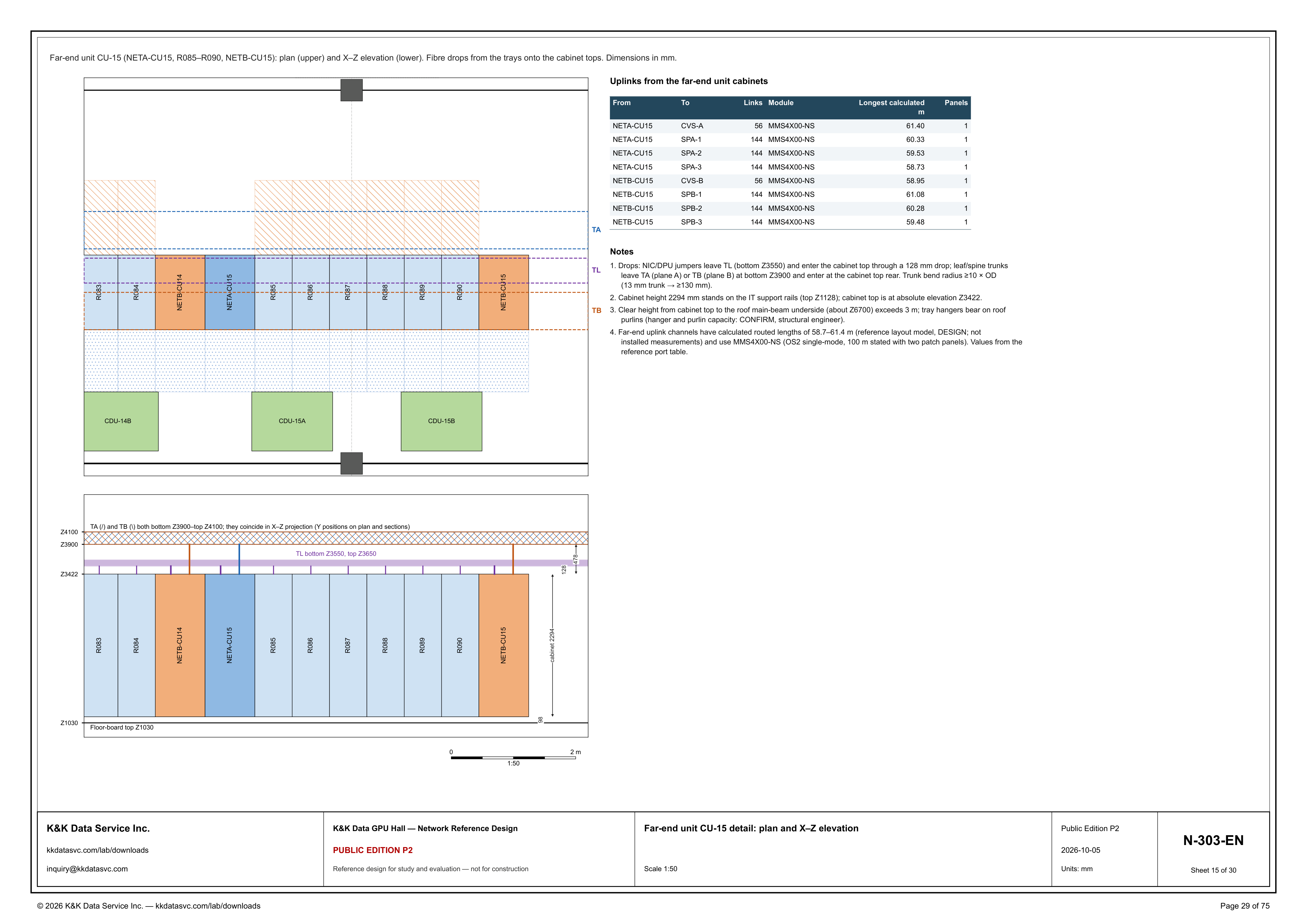
N-303-EN is the far-end unit detail, drawn at 1:50. The line under the top border names the unit and the two views: Far-end unit CU-15 (NETA-CU15, R085–R090, NETB-CU15): plan (upper) and X–Z elevation (lower). Fibre drops from the trays onto the cabinet tops. Dimensions in mm. The plan's cabinet row is R083, R084, NETB-CU14, NETA-CU15, R085, R086, R087, R088, R089, R090 and NETB-CU15. The header's parentheses name NETA-CU15, R085–R090 and NETB-CU15. R083, R084 and NETB-CU14 are printed on that row to the left of NETA-CU15. CDU-14B, CDU-15A and CDU-15B are drawn on the TB side of the row. Dashed lines are labeled TA above the cabinets, TL along the row and TB on the CDU side. The lower view repeats that row: R083, R084, NETB-CU14, NETA-CU15, R085, R086, R087, R088, R089, R090 and NETB-CU15, with a graphic scale marked 0 to 2 m at 1:50. The detail is part of the GPU hall reference.
Uplinks from the far-end unit cabinets
The table at the upper right is titled Uplinks from the far-end unit cabinets. The columns are From, To, Links, Module, Longest calculated m and Panels. Module is MMS4X00-NS on every row, and Panels is 1 on every row. From NETA-CU15 the rows are CVS-A, 56 links, longest calculated 61.40 m; SPA-1, 144 links, 60.33 m; SPA-2, 144 links, 59.53 m; and SPA-3, 144 links, 58.73 m. From NETB-CU15 the rows are CVS-B, 56 links, 58.95 m; SPB-1, 144 links, 61.08 m; SPB-2, 144 links, 60.28 m; and SPB-3, 144 links, 59.48 m. The CVS destination on each side is the 56-link row. Each SPA row and each SPB row is 144 links. Reading down the SPA rows, the longest-calculated values are 60.33 m, then 59.53 m, then 58.73 m. Reading down the SPB rows, they are 61.08 m, then 60.28 m, then 59.48 m. Among the eight values, 61.40 m on NETA-CU15 to CVS-A is the largest, and 58.73 m on NETA-CU15 to SPA-3 is the smallest. Note 4 states these far-end uplink channels as calculated routed lengths of 58.7–61.4 m (reference layout model, DESIGN; not installed measurements) and names the module MMS4X00-NS (OS2 single-mode, 100 m stated with two patch panels). The note says the values come from the reference port table. The Panels column is the cell that prints 1. The module statement in the same note is the line that says 100 m stated with two patch panels. NETA-CU15 is the From cabinet for CVS-A, SPA-1, SPA-2 and SPA-3. NETB-CU15 is the From cabinet for CVS-B, SPB-1, SPB-2 and SPB-3.
Drops, elevations, and the open check
Note 1 separates the two drops onto the cabinet top. NIC/DPU jumpers leave TL (bottom Z3550) and enter the cabinet top through a 128 mm drop. Leaf/spine trunks leave TA (plane A) or TB (plane B) at bottom Z3900 and enter at the cabinet top rear. Trunk bend radius is at least 10 × OD, and the note's example is a 13 mm trunk → ≥130 mm. The elevation draws TA and TB as one band. The caption states that TA (/) and TB (\) both run bottom Z3900–top Z4100 and coincide in X–Z projection, with Y positions on the plan and on sections. TL is labeled bottom Z3550, top Z3650. The elevation dimensions 128 from the cabinet top at Z3422 up to the TL bottom, and 478 from that cabinet top up to the TA/TB bottom at Z3900. The view draws drops from the tray bands down to the cabinet tops, and it draws the longer drops from the TA/TB band to NETA-CU15 and to NETB-CU15. Note 2 places the cabinet: height 2294 mm stands on the IT support rails (top Z1128), and the cabinet top is at absolute elevation Z3422. The elevation also dimensions 98 from floor-board top Z1030 up to the cabinet base and labels the cabinet body 2294. Z1128 plus that 2294 mm cabinet height is the stated top Z3422, and Z1030 plus the drawn 98 is Z1128. Z3422 plus 128 is the TL bottom Z3550, and Z3422 plus 478 is the TA/TB bottom Z3900. Note 3 is the open item overhead: clear height from the cabinet top to the roof main-beam underside (about Z6700) exceeds 3 m, and the tray hangers bear on roof purlins. Hanger and purlin capacity is marked CONFIRM, structural engineer.
Status
The title block dates the sheet 2026-10-05 and issues it as Public Edition P2, number N-303-EN, sheet 15 of 30, scale 1:50, units mm. The sheet title is Far-end unit CU-15 detail: plan and X–Z elevation. The status line reads: reference design for study and evaluation — not for construction. Note 4 marks the uplink lengths as calculated routed lengths of the reference layout model (DESIGN), not installed measurements, taken from the reference port table. It states the range 58.7–61.4 m and the module MMS4X00-NS, OS2 single-mode, 100 m stated with two patch panels. Note 3 leaves hanger and purlin capacity as CONFIRM for the structural engineer. The drawing is part of the Public Edition P2 network reference design.
Sheet guide — the devices on this drawing
CU-15 — plan upper, X–Z elevation lower
The line under the border names the subject: Far-end unit CU-15 (NETA-CU15, R085–R090, NETB-CU15): plan (upper) and X–Z elevation (lower). Fibre drops from the trays onto the cabinet tops. Dimensions in mm. The upper drawing is the plan and the lower drawing is the elevation.
R083, R084, NETB-CU14 — cabinets left of the unit
R083, R084 and NETB-CU14 are printed at the left of the plan row, before NETA-CU15. The header names the unit as NETA-CU15, R085–R090 and NETB-CU15. The elevation repeats R083, R084 and NETB-CU14 at the left of the lower view.
NETA-CU15 — R085–R090 and NETB-CU15
The plan row for the named unit is NETA-CU15, R085, R086, R087, R088, R089, R090 and NETB-CU15. NETA-CU15 sits just after NETB-CU14. NETB-CU15 sits after R090, at the right end of the row. The uplink table lists NETA-CU15 to CVS-A, SPA-1, SPA-2 and SPA-3, and NETB-CU15 to CVS-B, SPB-1, SPB-2 and SPB-3.
CDU-14B, CDU-15A, CDU-15B — CDU row on the plan
CDU-14B, CDU-15A and CDU-15B are drawn on the TB side of the plan, below the cabinet row. CDU-14B is the left block, CDU-15A the middle block and CDU-15B the right block. The header's unit list is NETA-CU15, R085–R090 and NETB-CU15. The CDU labels are on the plan, under that row.
TA / TL / TB — tray lines on the plan
Three dashed tray lines cross the plan. TA is the line above the cabinets, TL is the line along the cabinet row, and TB is the line on the CDU side of the row. Note 1 names TA as plane A and TB as plane B. The elevation caption says the Y positions of TA and TB are on this plan and on the sections, because the two trays coincide in the X–Z view.
Uplink table — NETA-CU15 and NETB-CU15
Uplinks from the far-end unit cabinets. NETA-CU15 to CVS-A is 56 links, longest calculated 61.40 m. SPA-1, SPA-2 and SPA-3 are 144 links each, at 60.33 m, 59.53 m and 58.73 m. NETB-CU15 to CVS-B is 56 links, at 58.95 m. SPB-1, SPB-2 and SPB-3 are 144 links each, at 61.08 m, 60.28 m and 59.48 m. Every row is module MMS4X00-NS, and the Panels cell is 1.
Notes 1–4 — drops, rails, CONFIRM and DESIGN
Note 1: NIC/DPU jumpers leave TL (bottom Z3550) through a 128 mm drop into the cabinet top; leaf/spine trunks leave TA (plane A) or TB (plane B) at bottom Z3900 and enter at the cabinet top rear. Bend radius is at least 10 × OD (13 mm trunk → ≥130 mm). Note 2: cabinet height 2294 mm on rails at top Z1128, cabinet top Z3422. Note 3: clear height exceeds 3 m to about Z6700, and hanger and purlin capacity is CONFIRM, structural engineer. Note 4: calculated routed lengths of 58.7–61.4 m, MMS4X00-NS (OS2 single-mode, 100 m stated with two patch panels), from the reference port table; DESIGN, not installed measurements.
TL / TA / TB — drops on the X–Z elevation
The X–Z elevation draws TA and TB as one band, bottom Z3900 and top Z4100, because the caption says TA (/) and TB (\) coincide in X–Z projection. TL is the lower band, bottom Z3550 and top Z3650. The view dimensions 128 from cabinet top Z3422 up to the TL bottom, and 478 from that top up to Z3900. The longer drops run from the TA/TB band down to NETA-CU15 and to NETB-CU15. Note 1 puts the NIC/DPU jumpers on the 128 mm drop from TL and the leaf/spine trunks in at the cabinet top rear.
Elevation cabinets — 2294 mm, top Z3422
The elevation labels the cabinet body 2294 and dimensions 98 from floor-board top Z1030 up to the cabinet base. Note 2 states cabinet height 2294 mm on the IT support rails (top Z1128), with the cabinet top at absolute elevation Z3422. This view repeats R083, R084, NETB-CU14, NETA-CU15, R085, R086, R087, R088, R089, R090 and NETB-CU15. The graphic scale is marked 0 to 2 m at 1:50. Z1030 plus the drawn 98 is Z1128, and Z1128 plus 2294 is the stated top Z3422.
N-303-EN — title block, sheet 15 of 30
The title block names the sheet Far-end unit CU-15 detail: plan and X–Z elevation, at scale 1:50, units mm, number N-303-EN, sheet 15 of 30. The edition cell reads Public Edition P2, dated 2026-10-05. The status line reads: reference design for study and evaluation — not for construction.
Get the full drawing set
This sheet is one page of the GPU Hall Network Reference Design — Public Edition P2 (75 pages, 1.6 MB) — a direct PDF download with a published SHA-256 checksum, no registration. The complete coordinated set is on the downloads page. Background guides: data center one-line diagrams · GB300 NVL72 facility requirements · liquid cooling and CDU design.
Questions about any device or parameter on this sheet: inquiry@kkdatasvc.com or the contact page.