
Data Center Lab · Reference Designs · Network
Sheet N-311-EN: Clearances where section A-A cuts CDU-08A and GPU cabinets R043/R044
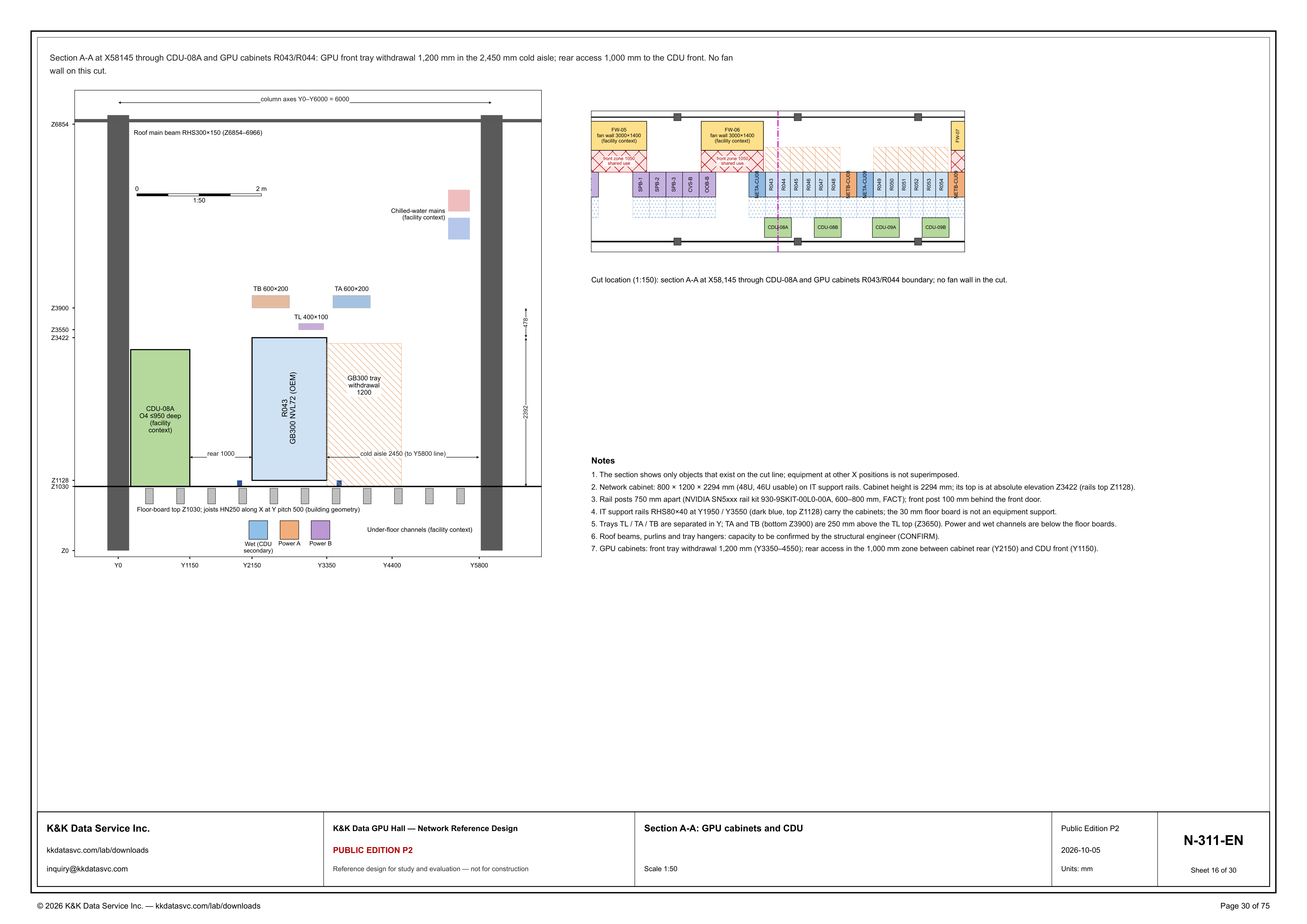
Section A-A at X58145 is the clearance cut through CDU-08A and GPU cabinets R043/R044 boundary: the section draws R043, with 1,200 mm of GB300 tray withdrawal inside the 2,450 mm cold aisle, 1,000 mm of rear access to the CDU front, and no fan wall on this cut.
Design Development — Public Edition P1: a reference design for study and evaluation, not a construction issue, not sealed by an Engineer of Record.
Scroll or pinch to zoom, drag to pan, click a highlighted device for its explanation. Vector drawing — it stays sharp at any magnification.
← N-303-EN · All network sheets · N-312-EN →
What this sheet shows
N-311-EN is building section A-A at 1:50. A key plan at 1:150 locates the cut. The sentence under the top border gives the station and the clearances together: Section A-A at X58145 through CDU-08A and GPU cabinets R043/R044; GPU front tray withdrawal 1,200 mm in the 2,450 mm cold aisle; rear access 1,000 mm to the CDU front; no fan wall on this cut. On the section, CDU-08A is the block labeled O4 ≤950 deep (facility context), and R043 is the block labeled GB300 NVL72 (OEM). The hatch on the cold-aisle side of R043 reads GB300 tray withdrawal 1200. The dimension beyond that hatch reads cold aisle 2450 (to the Y5800 line). The dimension in the gap reads rear 1000. The key-plan caption writes the station as X58,145 and names the cut as the boundary of GPU cabinets R043/R044, with no fan wall in the cut. Note 1 states the limit on the picture: the section shows only objects that exist on the cut line; equipment at other X positions is not superimposed. The dimension at the top of the section reads column axes Y0–Y6000 = 6000. The section labels the Y lines Y0, Y1150, Y2150, Y3350, Y4400 and Y5800, and the Z lines Z0, Z1030, Z1128, Z3422, Z3550, Z3900 and Z6854. Units are mm.
Clearances on this cut
Note 7 names the two service zones with Y coordinates. The front tray withdrawal is 1,200 mm, from Y3350 to Y4550. The rear access is the 1,000 mm zone between the cabinet rear at Y2150 and the CDU front at Y1150. The header places that 1,200 mm withdrawal inside the 2,450 mm cold aisle, and the section dimensions the aisle as 2450 to the Y5800 line. Subtracting 2,450 from Y5800 lands on Y3350, which is where note 7 starts the withdrawal, and the header already places that withdrawal in the cold aisle. The axis also marks Y0, Y4400 and the column line at Y6000. A vertical dimension on the right of the section prints 2392 and 478. The same two figures equal the differences of elevations marked on the cut. Note 5 puts TA and TB bottoms at Z3900, and Z3900 minus Z3422 is 478. The floor-board top is Z1030, and Z3422 minus Z1030 is 2392. The section also marks Z3550, Z1128, Z0 and Z6854. Nothing on this sheet calls R043 an 800 × 1200 × 2294 cabinet. That size is note 2, and note 2 is about the network cabinet: 800 × 1200 × 2294 mm (48U, 46U usable) on IT support rails, cabinet height 2294 mm, top at absolute elevation Z3422, rails top Z1128. The key plan shows where those network cabinets sit relative to this cut. NETA-CU08 is drawn beside R043, then R044, R045, R046, R047, R048, NETB-CU08, NETA-CU09, R049, R050, R051, R052, R053, R054 and NETB-CU09. The dashed cut is at the R043/R044 boundary, through CDU-08A, not through a fan wall. FW-05 and FW-06 are drawn on that plan, each 3000×1400 and marked facility context, each with a front zone 1050 marked shared use, and FW-07 is labeled at the right. The header and the cut caption both say there is no fan wall on this cut, so the 1050 front zones are not on section A-A.
Rails, trays, and what is still open
Note 4 names what actually carries the cabinets. IT support rails RHS80×40 at Y1950 / Y3550, drawn dark blue, with top at Z1128, carry the cabinets. The same note says the 30 mm floor board is not an equipment support. The floor-board top is Z1030, and the floor label reads: joists HN250 along X at Y pitch 500 (building geometry). Below that board the section shows under-floor channels, marked facility context: Wet (CDU secondary), Power A and Power B. Note 5 puts the same services in words: power and wet channels are below the floor boards. Overhead, note 5 separates trays TL, TA and TB in Y. TA and TB, bottom Z3900, are 250 mm above the TL top at Z3650. The section labels them TL 400×100, TA 600×200 and TB 600×200, with TB toward the CDU side of the cabinet and TA and TL toward the cold aisle. The sheet also marks Z3550. Up high, the chilled-water mains are drawn and marked facility context; the sheet gives them no size on this cut. The roof main beam is labeled RHS300×150 (Z6854–6966). Note 6 leaves its capacity open, and the note is wider than the beam: roof beams, purlins and tray hangers, capacity to be confirmed by the structural engineer (CONFIRM). Note 3 is a different kind of mark. Rail posts are 750 mm apart, the kit is NVIDIA SN5xxx rail kit 930-9SKIT-00L0-00A, the stated range is 600–800 mm, and the note marks that range FACT. The front post is 100 mm behind the front door. The note does not say those posts are the GB300 tray slides. CDU-08A, the chilled-water mains and the under-floor channels are marked facility context. FW-05 and FW-06 are each labeled fan wall 3000×1400 (facility context), with front zone 1050 shared use. FW-07 is only the ID: the sheet prints no fan-wall label, no 3000×1400 and no facility-context mark on it.
Status
The title block issues the drawing as Public Edition P2, number N-311-EN, sheet 16 of 30, dated 2026-10-05, scale 1:50, units mm. The sheet title is Section A-A: GPU cabinets and CDU. The status line reads: reference design for study and evaluation — not for construction. The open item on the sheet is note 6: roof beams, purlins and tray hangers, capacity to be confirmed by the structural engineer (CONFIRM). Note 3 marks the rail-kit range 600–800 mm as FACT, on kit 930-9SKIT-00L0-00A. Note 2 states the network-cabinet envelope and the elevations Z3422 and Z1128; it does not assign that envelope to R043. The sheet is part of the Public Edition P2 network reference design for the GPU hall reference.
Sheet guide — the devices on this drawing
CDU-08A — O4 ≤950 deep, facility context
CDU-08A is the block on the CDU side of the cut, labeled O4 ≤950 deep and marked facility context. Note 7 places the CDU front at Y1150. The 1,000 mm rear-access zone runs from that front to the cabinet rear at Y2150. The key plan shows CDU-08A on this cut, and CDU-08B, CDU-09A and CDU-09B further along the row.
R043 — GB300 NVL72 (OEM)
R043 is the GPU cabinet drawn on the cut, labeled GB300 NVL72 (OEM). The header names the cut through GPU cabinets R043/R044, and the key-plan caption places it at their boundary. Note 7 puts the cabinet rear at Y2150. Note 2's 800 × 1200 × 2294 mm network-cabinet envelope is not printed on this block.
GB300 tray withdrawal — 1,200 mm in the cold aisle
The hatch in front of R043 is labeled GB300 tray withdrawal 1200. Note 7 places that front tray withdrawal at Y3350–4550, 1,200 mm. The dimension beside it reads cold aisle 2450 (to the Y5800 line), and the header places the withdrawal in that 2,450 mm cold aisle. Subtracting 2,450 from Y5800 lands on Y3350.
Rear access — 1,000 mm, Y2150 to Y1150
The dimension in the gap between R043 and CDU-08A reads rear 1000. Note 7 calls this the rear access: the 1,000 mm zone between the cabinet rear at Y2150 and the CDU front at Y1150. The header states the same clearance as rear access 1,000 mm to the CDU front.
TL / TA / TB — trays separated in Y
Note 5 says trays TL, TA and TB are separated in Y. The section labels TL 400×100, TA 600×200 and TB 600×200. TA and TB have their bottoms at Z3900, 250 mm above the TL top at Z3650. TB is drawn toward the CDU side of R043; TA and TL are drawn toward the cold aisle. The sheet also marks Z3550.
RHS80×40 rails — Y1950 / Y3550, top Z1128
Note 4 says IT support rails RHS80×40 at Y1950 / Y3550 carry the cabinets. They are the dark blue marks, top Z1128. The same note says the 30 mm floor board is not an equipment support. The floor label gives the board top as Z1030 and joists HN250 along X at a Y pitch of 500, called building geometry. Under the board are Wet (CDU secondary), Power A and Power B, marked facility context. Note 5 says power and wet channels are below the floor boards.
Roof beam RHS300×150 — Z6854–6966, capacity CONFIRM
The beam across the top of the section is labeled Roof main beam RHS300×150 (Z6854–6966). The column-axis dimension beside it reads Y0–Y6000 = 6000. Note 6 does not treat that beam as confirmed: roof beams, purlins and tray hangers, capacity to be confirmed by the structural engineer (CONFIRM).
Chilled-water mains — facility context
Two blocks high in the section, above the trays and toward the cold-aisle column, are labeled Chilled-water mains (facility context). The sheet prints no pipe size for them on this cut. They sit in the same class of mark as CDU-08A and the under-floor channels: drawn so the cut can be read, and labeled facility context.
Cut location — X58,145 at R043/R044
The plan at 1:150 is the locator, not a second section. Its caption reads: section A-A at X58,145 through CDU-08A and GPU cabinets R043/R044 boundary; no fan wall in the cut. The row on that plan runs SPA 3, SPB-1, SPB-2, SPB-3, CVS-B, OOB-B, NETA-CU08, R043 through R054 with NETB-CU08 and NETA-CU09 between the rack groups, and NETB-CU09. FW-05 and FW-06, each 3000×1400, sit off the cut with a front zone 1050 marked shared use. FW-07 is labeled at the right.
Notes 1–7 — what the cut includes
Note 1 keeps other X positions off the section. Note 2 gives the network cabinet as 800 × 1200 × 2294 mm, 48U with 46U usable, top Z3422, rails top Z1128. Note 3 gives rail posts 750 mm apart on kit 930-9SKIT-00L0-00A, range 600–800 mm, marked FACT, front post 100 mm behind the front door. Note 4 puts the carrying rails at Y1950 / Y3550. Note 5 separates the trays and puts power and wet channels below the floor boards. Note 6 is the open item: capacity CONFIRM. Note 7 states the 1,200 mm withdrawal at Y3350–4550 and the 1,000 mm rear zone from Y2150 to Y1150.
Get the full drawing set
This sheet is one page of the GPU Hall Network Reference Design — Public Edition P2 (75 pages, 1.6 MB) — a direct PDF download with a published SHA-256 checksum, no registration. The complete coordinated set is on the downloads page. Background guides: data center one-line diagrams · GB300 NVL72 facility requirements · liquid cooling and CDU design.
Questions about any device or parameter on this sheet: inquiry@kkdatasvc.com or the contact page.