
12,000 kW [MODELED] against 12,711 kW [MODELED] of protected load is a 711 kW [MODELED] shortfall. 14,000 kW [MODELED] against the same 12,711 kW is a 1,289 kW [MODELED] surplus. Both figures are the remainder after the same stacked sequence: take one complete path or system out for maintenance, then fault a single uninterruptible-supply module on what is left. The first remainder belongs to strict low-voltage 2N with fourteen 2 MW [MODELED] units. The second belongs to the twelve-unit 3-to-make-2 arrangement. The arrangement carrying less installed capacity is the one that still has 14 MW [MODELED] in that case.
Maintenance-Plus-Fault Leaves 12 MW on 2N, 14 MW on 3-to-Make-2
The stacked case is not exotic. It is one planned outage and one unplanned failure overlapping, which is the condition any concurrently maintainable design is expected to state a position on. The Gate 1 closure review runs it against all three candidate topologies rather than against one route only.
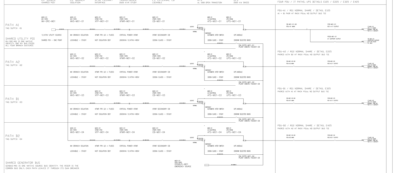
Strict 2N in this study is sixteen transformers, fourteen 2 MW units and a five-minute battery floor of 3.172 MWh [MODELED]. Its single-module-fail capacity is comfortable: thirteen remaining units still give 26 MW [MODELED] of aggregate capability, and the closure review accepts that. The stacked case is where it fails, and it fails by arithmetic rather than by degradation. One path in maintenance leaves seven units. One of those is then faulted. Six units at 2 MW is 12,000 kW.
The three-system route in the same study is fourteen transformers, twelve 2 MW units and a five-minute battery floor of 2.379 MWh [MODELED]. One system in maintenance leaves two systems. A single module fault on one of those leaves eight units on one system and six on the other. 8 + 6 = 14 MW. That is 2,000 kW [MODELED] more than the strict 2N remainder, and 1,289 kW above the protected load.
3-to-Make-2 Retires a Third of the Fleet, Not a Half
Redundancy in the strict 2N arrangement is spent on duplicating whole paths, so a maintenance outage retires half the fleet in one action. The 3-to-make-2 arrangement spreads the same protected load across three independent systems and adds a fourth module inside each, so a system-level maintenance outage retires a third rather than a half, and the single module fault then removes one unit from a larger remainder.
Gate 1 priced that spreading as about 25 % [MODELED] less uninterruptible-supply and transformer capacity than strict 2N. The quantity derivation that closed later prices the real save at 14 % [MODELED]: twelve modules against fourteen, 24,000 kW [MODELED] installed against 28,000 kW [MODELED], 189 % [MODELED] of protected load against 220 % [MODELED]. The 25 % talking point was a nine-unit count. That count is arithmetically rejected against 12.711 MW and is treated in its own note. The twelve-unit version is what the 14 MW remainder describes.
A later load column widens the strict 2N hole from 711 kW to 1,085 kW [MODELED] against 13,085 kW [MODELED] of protected load. The same column still sits inside the three-system 14 MW remainder. That comparison is a capacity result. It does not freeze the three-system route.
The 14 MW Remainder Is Capacity, Not a Transfer Proof
The closure review accepts the 14,000 kW as capacity only. It does not substitute for a rack pairing matrix or a demonstrated load-transfer proof. Separately, the three systems must not be capable of being removed together by one medium-voltage or ring event. Three systems that share a medium-voltage identity are not three systems. With any one system out, two healthy systems total 16 MW [MODELED] against the same 12.711 MW, on the same condition.
The 1,289 kW surplus is not headroom for growth. It is the margin that allows the necessary cooling-distribution load to stay energised rather than be shed. That is the specific concession the shared engineering register refuses to make on the strict 2N side: the 711 kW shortfall must not be closed by assuming necessary liquid-cooling load can be dropped. 12,711 kW of protected load closes as 12,000 + 585 kW [MODELED] + 126 kW [MODELED]. Six 2 MW modules cover the first term and nothing else.
The comparison is therefore not 14,000 against 12,000 kW of capacity. It is whether the load-shed table for the stacked case has to contain cooling-distribution equipment at all. On the strict 2N side, on the current record, it does.
Limits and open items
Confirmed: 12,711 kW of protected load closes as 12,000 + 585 + 126; the strict 2N stacked case leaves 12,000 kW and is 711 kW short; the three-system arrangement retains 14,000 kW in its equivalent stacked case; the deficit may not be closed by default shedding of necessary liquid-cooling load. [FACT]
Modelled and explicitly not frozen: the unit counts themselves — sixteen transformers and fourteen units against fourteen transformers and twelve units — the five-minute battery floors of 3.172 and 2.379 MWh, the 96.5 % [MODELED] conversion efficiency and the 585 kW auxiliary allowance. The closure review admits these as conditionally frozen study values and prohibits purchase orders against them. The three-system route is a conditional study route under later errata, not a preferred, recommended or baseline selection. [MODELED]
Held: the rack pairing matrix and load-transfer proof for the three-system arrangement, the failure-domain separation that keeps the three systems independent of a single medium-voltage event, and the customer's contractual position on whether each of A and B independently carries 100 % of protected load. [HOLD]
Nothing here constitutes Engineer of Record review, equipment selection, procurement release or a demonstration on installed plant.
Which System Pairs With Which at Each Rack
One contract sentence reverses this comparison outright. The shared engineering register states that the three-system route is the path being deepened unless the customer contract fixes that each of A and B independently carries 100 % of protected load. In that case the design falls back to strict 2N with its 711 kW shortfall intact, and the shortfall becomes something to engineer around rather than avoid.
That makes the pairing matrix the item to close first. The question for it is specific: with graphics processing racks presenting two power-supply inputs and three systems available to feed them, which system pairs with which at each rack, and does that mapping still hold after any one system is out?
© 2026 K&K Data Service Inc. All rights reserved. Reproduction or republication is permitted only with clear attribution to K&K Data Service Inc. and a working hyperlink to the canonical URL of this article. Excerpts must preserve the technical context, maturity labels, assumptions, and limitations. No excerpt may imply project approval, field validation, certification, or endorsement that the original article does not state.
Source: K&K Data Service Inc., “3-to-Make-2 UPS Retains 14 MW in the Maintenance-Plus-Fault Case,” https://www.kkdatasvc.com/lab/ups-battery-and-generation/distributed-redundant-still-has-14-mw-in-the-same-stacked-case/.
Request the Public Calculation Note. If your project record shows a different result, or the same failure domain under another name, we want to see it. Email inquiry@kkdatasvc.com or use the contact page.