
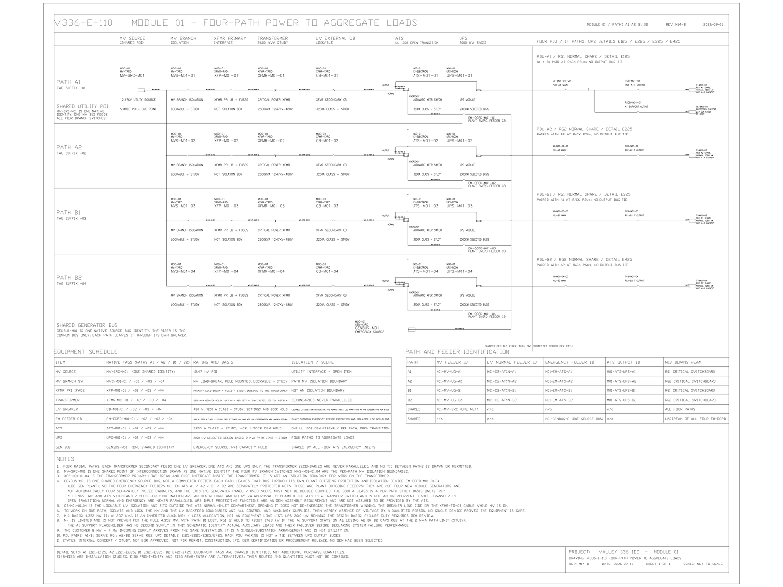
A coolant contamination, a particulate burst, or gel formation in one cooling zone is supposed to stay in that zone. Draw a tie pipe to the next zone and the same event becomes a site event. Three cooling zones and a three-system electrical arrangement invite a one-to-one mapping anyway, because the mapping is cheap to draw and easy to defend in a meeting. The two systems build redundancy in opposite directions — the cooling basis puts it as a tie bus being an asset on the electrical side and a tie pipe being a liability on the liquid side — so aligning their domain boundaries imports each one's worst property into the other. This concerns where boundaries fall, not how much equipment sits inside them.
A Matching Count of Three Is Not a Mapping Reason
The cooling study is organised as three zones, each carrying its own redundancy group. In the symmetric variant the zones are load-equal, which makes ring segments, valve counts, spares and commissioning scripts identical across all three, and makes the piping and rack-branch details geometrically congruent so that one set is drawn and instanced three times. Zone thermal load in that variant is 3,928 kW [MODELED] at a liquid fraction of 0.95 [MODELED]. The largest single cooling event is therefore about one third of site IT — roughly 4 MW [MODELED], or about 31 racks at 130 kW [MODELED].
A three-system electrical arrangement also has three of something. Laying one over the other makes both drawings legible, makes the rack pairing matrix trivial to write, and gives every zone a single owner on the electrical side. Nothing about that is careless. It is the arrangement a competent drafter reaches for.
A Tie Bus Is an Asset; a Tie Pipe Is a Liability
Tie pipes between cooling zones are excluded, and the basis gives arithmetic rather than preference as the reason. Capacity-sharing benefit is zero, because the zones are already load-equal and each already carries its own spare unit. The cost is certain: coolant contamination, particulates or gel formation in any one zone spreads across the interconnection and promotes a single-zone event to a site event; hydraulic interconnection makes pressure and flow distribution a cross-zone balancing problem and raises isolation complexity by an order of magnitude; and it introduces six large valves that must be normally closed and must be proven normally closed, each of which is a new single point [FACT].
From that the record draws the general statement: fault isolation is worth more than capacity sharing on the liquid side, and this is the key difference from the electrical side, where the tie is a benefit.
So the two systems want opposite things at the boundary. Electrical redundancy is largely built by connecting — parallel sources, tie breakers, transfer paths. Liquid redundancy on this design is built by refusing to connect. A boundary that is correct for one discipline is wrong for the other. Making them coincide means one of the two gives up the property it was drawn for.
Dual feed already rules the map out
Two independent records rule out the one-to-one map before any of the above is weighed.
On the electrical side, the cross-check states that each coolant distribution unit requires an A/B dual supply, and that changing the unit count changes both the number of mechanical distribution branches and the failure-domain pairing matrix [FACT]. A zone fed from one electrical system would leave its units single-fed, which is the opposite of what the requirement says.
On the failure-matrix side, the three-system arrangement carries an explicit row: critical liquid-cooling load must be spread across at least two electrical systems, the evidence required to close it is named as the electrical-to-cooling failure domain mapping, and the row also records that shared controls and shared pipe segments remain a common cause even after the electrical side has been distributed [FACT]. That last clause matters. Distributing the electrical feeds is necessary. It does not by itself decouple the two systems.
Limits and open items
Confirmed: no tie pipes between cooling zones; each distribution unit requires a dual supply; critical cooling load must be spread across at least two electrical systems; the electrical-to-cooling domain mapping is an open evidence item rather than a closed one. [FACT]
Study values, not frozen: the three-zone arrangement and its unit-count branches, including the 11 × 1.5 MW [MODELED] study base; the 3,928 kW zone thermal load; the one-third site exposure of roughly 4 MW and the approximate rack count behind it; and the electrical arrangement itself, which is not selected. [MODELED]
Open: the owner's decision on the maximum acceptable simultaneous cooling-loss domain; the rack-level pairing matrix and its machine verification; a quantified thermal ride-through window; and the selection of the electrical arrangement. [HOLD]
Two conditions would change what this note is about. If the maximum acceptable cooling-loss domain is set at one sixth rather than one third, the zone count goes from three to six, and a one-to-one map against three electrical systems fails on counting alone — the temptation disappears rather than the reasoning changing. Separately, the cooling unit count is held across three branches, and only one of them divides evenly into three zones. If the fifteen-unit branch is selected, the pairing matrix is rebuilt regardless of what the electrical side does.
No mapping, count or boundary here has been reviewed or sealed by an Engineer of Record. None is released for purchase. None describes an installed system.
Coincidence is not a principle
Zone count and electrical system count are each decided for their own reasons, at different times, by different disciplines. When they happen to match, the match is a coincidence. Treating a coincidence as a design principle is how a coupled domain gets built without anyone choosing to build one. The discipline that costs nothing is to draw both boundaries on the same sheet and let them visibly disagree. When the maximum acceptable simultaneous cooling-loss domain is finally set, will the electrical system count be re-derived from it — or quietly used to constrain it?
© 2026 K&K Data Service Inc. All rights reserved. Reproduction or republication is permitted only with clear attribution to K&K Data Service Inc. and a working hyperlink to the canonical URL of this article. Excerpts must preserve the technical context, maturity labels, assumptions, and limitations. No excerpt may imply project approval, field validation, certification, or endorsement that the original article does not state.
Source: K&K Data Service Inc., “Do Not Map Electrical Systems 1:1 onto Cooling Zones,” https://www.kkdatasvc.com/lab/electrical-architecture-and-failure-domains/do-not-map-electrical-systems-1-1-onto-cooling-zones/.
Discuss This Constraint. If your project record shows a different result, or the same failure domain under another name, we want to see it. Email inquiry@kkdatasvc.com or use the contact page.