
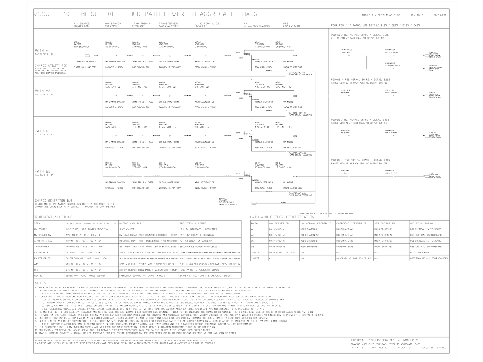
The sales number is 12 MW [TARGET] of billable IT. The UPS is not sized on that number. It is sized on 12.711 MW [MODELED] of protected load — 711 kW [MODELED] of cooling-distribution plant and path loss that cannot be dropped while the IT still has power. Divide the 12 MW sales number into 2,000 kW modules and the path count is a whole number. Protected load is not: it is seven modules per path, fourteen in total [MODELED]. Sizing on the billable figure is listed among the prohibited shortcuts.
Cooling and Path Loss Cannot Drop While IT Has Power
Two components, both carried as assumptions rather than as facts.
The larger is 385 kW [MODELED] for coolant-distribution-unit pumping, drives, controls and internal fans, entered as eleven units at 35 kW and marked as pending equipment data. The smaller is 200 kW [MODELED] for facility water circulation pumps that sit on the UPS, reverse-calculated from a 9.6 MW liquid-cooled duty at an 8 K temperature rise, 40 m head and 0.70 combined efficiency — which yields roughly 160 kW and was taken at 200 kW to include a standby pump on standby power. Those give 585 kW [MODELED] of auxiliary load. 1.0 % of the sum of IT and auxiliary load gives 126 kW [MODELED] of distribution loss. The summation 12,000 + 585 + 126 = 12,711 kW closes.
The distinction that matters is not accuracy but membership. A pump that keeps coolant moving during a transfer is not a convenience load. If it drops, the thermal clock starts even though the IT equipment still has power. The closure record makes the same point from the other direction when it refuses to let the auxiliary allowance be treated as sheddable by default. Membership in the protected load is therefore an engineering determination about what happens when the load is lost, not a category assigned by which panel the circuit happens to leave from.
UPS and Generation Are Sized on Different Loads
UPS capacity answers to protected load. Generation capacity answers to facility demand, carried at 14.391 MW [MODELED]. Those are different numbers because they cover different events. A UPS bridges the interval in which the facility has lost its source and the plant has not yet picked up, so it only has to carry what must not be interrupted. Generation carries the site once it has picked up, including mechanical plant that can tolerate the interruption but not its continuation.
Reading one denominator into the other machine is the failure mode this rule exists to prevent, and it can go in either direction. Generation sized on protected load is short by the whole mechanical and house allowance. A UPS sized on facility demand is oversized by the same amount into a lower-efficiency operating band.
Module Count Lands Where the Efficiency Input Is Wrong
Protected load is converted into UPS input demand using an assumed double-conversion efficiency of 96.5 % [MODELED], which gives 461 kW [MODELED] of UPS loss and 13.172 MW [MODELED] of input demand. Under strict two-path redundancy each path is sized for the full 12.711 MW, so seven 2,000 kW modules per path and fourteen in total. In normal operation, with dual-cord load split across both paths, each module then runs at 908 kW — 45.4 % of its rating [MODELED]. Only when one path is entirely lost do modules reach 1,816 kW, or 90.8 % [MODELED].
That is the loop worth naming. The 96.5 % figure is a near-full-load value. The record registers that actual double-conversion efficiency at 45 % to 53 % module loading typically falls 0.5 to 1.5 percentage points [SENSITIVITY] below it, with a direct effect on input demand and on the transformer count check. Running the arithmetic on the source inputs — this note's calculation, not a figure taken from the record — a full point of efficiency loss moves the UPS loss term from 461 kW to about 599 kW, roughly 138 kW [SENSITIVITY]. The heat-rejection basis independently prices half a point at about 65 kW [SENSITIVITY] on its own slightly different load figure, which is the same order.
So the module count produced by the sizing rule places the modules at an operating point where the efficiency input to that same rule is not the right one.
Limits and open items
Confirmed: UPS sizing follows protected load and generation follows facility demand; dividing the billable IT figure into whole modules is prohibited; the summation 12,000 + 585 + 126 = 12,711 kW closes. [FACT]
Modelled and unfrozen: 585 kW auxiliary, 126 kW path loss, 461 kW UPS loss, 13.172 MW input demand, the fourteen-module study quantity, and the 45.4 % and 90.8 % loading figures. The 385 kW coolant-distribution figure, 200 kW facility-pump figure, 1 % end-of-path loss and 96.5 % UPS efficiency remain unverified assumptions and may not be stated as procurement facts. None is released for purchase. [MODELED]
Open: written efficiency curves across the 45–53 % band; equipment data behind the 385 kW and 200 kW entries; the item-by-item controlled load schedule; and the owner's written position on module-level redundancy. The 96.5 % value may not be frozen. [HOLD]
A different conclusion would follow on the component side if the cooling reconciliation is accepted. That record reverse-calculates site secondary pumping at 46 kW [MODELED] with twelve [MODELED] pumps in parallel and 105 kW [MODELED] with eight [MODELED] pumps at full load under N−1, against the 385 kW carried here — 280 to 339 kW lower [MODELED] — which would put protected load near 12.37 to 12.43 MW [SENSITIVITY]. The same record forbids deducting that difference on its own. The module count survives that change and would only fall to three per system at a protected load of 12,000 kW [MODELED] exactly, which requires both the auxiliary and the loss allowance to vanish. A cooling ride-through requirement, if confirmed, moves 46 to 105 kW [SENSITIVITY] back the other way.
Nothing here has been reviewed or sealed by an Engineer of Record, and no quantity is released.
At What Loading Should the UPS Efficiency Be Read
Efficiency assumptions are usually challenged on whether the number is generous. The more useful challenge on this record is where on the curve it was read. A module count derived from a full-load efficiency, which then guarantees 45 % loading in every normal hour of the plant's life, has quietly evaluated its own input at a condition the design will rarely be in. When the efficiency curve arrives, the question to put to the electrical lead is not what the peak figure is — it is what the figure reads at 908 kW per module.
© 2026 K&K Data Service Inc. All rights reserved. Reproduction or republication is permitted only with clear attribution to K&K Data Service Inc. and a working hyperlink to the canonical URL of this article. Excerpts must preserve the technical context, maturity labels, assumptions, and limitations. No excerpt may imply project approval, field validation, certification, or endorsement that the original article does not state.
Source: K&K Data Service Inc., “UPS Sizing Follows Protected Load, Not the 12 MW Sales Number,” https://www.kkdatasvc.com/lab/electrical-architecture-and-failure-domains/we-sized-ups-on-protected-load-not-the-sales-number/.
Request the Public Calculation Note. If your project record shows a different result, or the same failure domain under another name, we want to see it. Email inquiry@kkdatasvc.com or use the contact page.