
The intuitive basis is 0.50 of rack load. The basis that applies is 1.25. They are not two readings of the same column. Anything sized on the halving intuition is sized at 40 % of what applies. Under single-path operation each cord of a dual-cord rack carries the whole rack, so the cord and its branch are sized on 100 % of rack load, with the continuous-load factor applied above that. This concerns the sizing basis at the end of the path, not the number of paths. It does not by itself settle conductor mass.
The Last Cord Is Sized for the Whole Rack
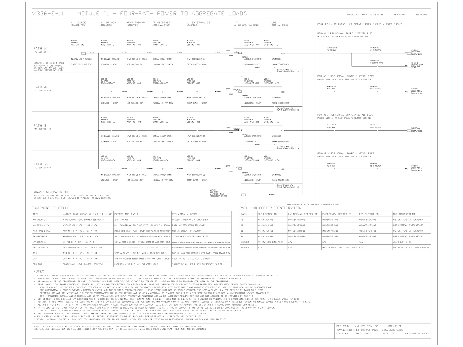
Strict two-path redundancy is defined in the architecture record as two complete paths, each independently carrying 100 % of the agreed IT load, with the two power supplies of each rack taking one path each [FACT]. The path-level low-voltage demand that follows is 13.172 MW [MODELED] — the whole 12.711 MW [MODELED] protected load divided by the 96.5 % [MODELED] UPS efficiency assumption, not half of it.
The failure matrix states the same thing at rack level rather than at path level. On a single UPS module fault, the affected side's first power supply loses its source and the second carries 100 % [FACT]. Nothing about that depends on choosing strict two-path redundancy. Under the three-system distributed arrangement the requirement appears as a pairing rule: a rack's two supplies must not both land on the system that withdraws. When one system does withdraw, the surviving cord again carries the rack. The record requires that pairing matrix to be checked by machine rather than by eye. It is the only thing standing between a nominal redundancy and a rack with both cords on one dead system.
So the per-cord basis is topology-independent. Whichever redundancy scheme is selected, the last cord is sized for the case where it is the only one.
The 1.25 Factor Applies Above the Full-Rack Basis
Above 100 %, the continuous-load factor of 1.25 applies wherever the load qualifies as continuous. The design basis applies it explicitly one level up: a 2,000 kW [MODELED] UPS output is 2,430 A [MODELED], and 2,430 × 1.25 = 3,038 A [MODELED], met by a 3,200 A [MODELED] frame or a 100 %-rated 3,000 A [MODELED] device. The same discipline follows the branch down to the tap.
Set the two bases side by side. Halving gives 0.50 of rack load. The applicable basis is 1.25. Anything sized on the halving intuition is sized at 40 % of what applies. Conductor cross-section does not scale linearly with ampacity across the whole range. This is not a claim that 2.5 times the basis means 2.5 times the copper. The point is which number goes into the ampacity column. The mass consequence follows from the conductor tables, not from this ratio.
The operating point is not the sizing case
The halving intuition comes from the normal operating point, which genuinely is about half. With dual-cord load split across both paths, each module in the strict two-path arrangement runs at 908 kW, or 45.4 % of rating [MODELED]. It only reaches 1,816 kW — 90.8 % [MODELED] — when the opposite path is lost. The half-load figure is real. It is simply not the sizing case. The two are separated by the one event the second path exists for.
What the confusion costs is not trunk capacity. Trunk and switchgear quantities are set by the upstream module count and are re-derived every time that count changes. The exposure is at the end of the path, where the two figures diverge and where nobody re-checks: the busway tap-off, the rack power distribution unit input device, and the cord. Those are also the items procured last, in bulk, and against a schedule rather than against a calculation.
Two things this does not mean. Adding the second path does not halve anything upstream either — installed UPS capacity in the strict two-path arrangement is 220 % of protected load [MODELED], which is the honest cost of the arrangement. And it does not make single-cord equipment the cheaper choice. Single-source loads then require a static transfer switch, which the same record identifies as a single point and recommends compressing toward zero rather than deploying as a site-wide layer.
Limits and open items
Confirmed: each path, and each cord, is sized on 100 % of the load it may have to carry alone; both power supplies of a rack may not land on one system; a static transfer switch introduced to serve single-source loads is itself a single point. [FACT]
Modelled and unfrozen: 13.172 MW path demand, the 12.711 MW protected load and 96.5 % efficiency behind it, 2,430 A and 3,038 A at the UPS output, 908 kW at 45.4 % and 1,816 kW at 90.8 % module loading, and the 220 % installed ratio. [MODELED]
Open: rack power density and the end-use voltage decision, which together set busway and distribution unit quantities and therefore the actual conductor mass; the rack-level pairing matrix and its load-transfer proof; the owner's written choice between two independent 100 % paths and distributed redundancy; and whether a given terminal load qualifies as continuous, which is a determination for the Engineer of Record against the applicable code and not a conclusion of this note. [HOLD]
A different conclusion follows for any branch whose load does not qualify as continuous: the 1.25 factor drops out and the basis becomes 1.00. That is still twice the halving intuition. The direction does not change — only the margin does.
No quantity, rating or arrangement here has been reviewed or sealed by an Engineer of Record. Nothing is released for purchase.
Was Ampacity Taken From the Split or the Single-Path Case
Dual-cord sizing has an awkward property: the normal-operation figure and the sizing figure are both correct, they differ by roughly a factor of two and a half, and a one-line drawing shows neither. Only one of them belongs in the ampacity column, and it is the less intuitive one. On the panel schedule currently in front of you, was that column derived from the normal split or from the single-path case?
© 2026 K&K Data Service Inc. All rights reserved. Reproduction or republication is permitted only with clear attribution to K&K Data Service Inc. and a working hyperlink to the canonical URL of this article. Excerpts must preserve the technical context, maturity labels, assumptions, and limitations. No excerpt may imply project approval, field validation, certification, or endorsement that the original article does not state.
Source: K&K Data Service Inc., “Each Dual-Cord Path Must Be Sized for Full Rack Load,” https://www.kkdatasvc.com/lab/electrical-architecture-and-failure-domains/dual-cord-is-not-half-the-copper/.
Discuss This Constraint. If your project record shows a different result, or the same failure domain under another name, we want to see it. Email inquiry@kkdatasvc.com or use the contact page.