
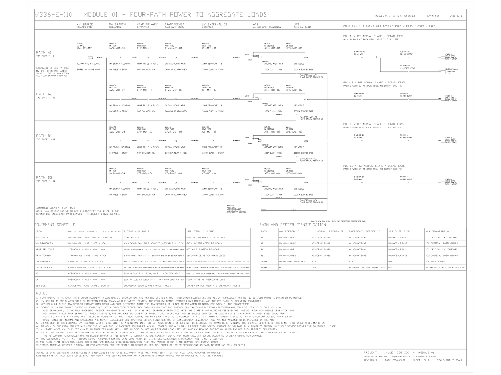
The site takes 12.47 kV [TARGET] service on two feeders, 8 MW [TARGET] and 7 MW [TARGET], drawn on the one-line as independent utility sources. Both feeders leave the same substation. A bus fault, a common protection misoperation, a substation transformer outage, or a shared right-of-way can take them together — and even while the substation stays up, neither feeder can carry the 14.391 MW [MODELED] facility load. That is not independent dual utility service, and it is not utility 2N [FACT].
The One-Line Shows Connectivity, Not Failure Domain
Two breakers, two cable routes, and two metering points read as dual utility service. That reading survived several document cycles. The question that ended it was narrow: name the events that remove both feeders at once. Every answer on that list is a common-cause event at or above the substation.
The architecture-decision record therefore listed the same-substation pair as an excluded incorrect statement. The later Gate 1 electrical closure froze the same point as a negative conclusion rather than a design feature: two feeders from one substation are not independent dual utility, and either feeder alone cannot carry the site.
The one-line is not wrong about connectivity. It is silent about failure domain. Availability claims that start from how many breakers appear on the drawing start in the wrong place. On the current record they have to start below the utility interface, because the service has a common substation failure domain regardless of breaker count.
Neither feeder carries the site
The recorded facility input upper limit is 15 MW [TARGET]. The two feeder allocations sum to that cap only when both are present. The study basis of 14.391 MW [MODELED] sits close under the cap, and each feeder by itself is smaller than the facility load.
Lose the 8 MW feeder and 7.391 MW [MODELED] remains unserved. Lose the 7 MW feeder and 6.391 MW [MODELED] remains unserved. In either case the surviving feeder does not carry the site. On-site generation picks up the deficit, or load is shed. That is a transfer sequence, not a degraded-utility mode, and it has to be designed, sequenced, and tested as one.
On-site generation is therefore the redundancy element for the single-feeder case. Its study basis is facility load, not IT load. The UPS-protected load of 12.711 MW [MODELED] sits downstream of the transformers. It does not change the arithmetic at the utility interface.
The 8 MW and 7 MW Feeders Are Not Interchangeable
An even split of the facility load puts 7.196 MW [MODELED] on each feeder. That overruns the smaller allocation by about 0.196 MW [MODELED] before any failure occurs. Steady-state load must be biased toward the 8 MW side. The visual symmetry of an A/B one-line is not available as an operating symmetry.
The split is not an operations preference. It is an engineering setting that still needs a load-flow check. The current record accepts the bias in principle and leaves the allocation itself open.
Low-voltage A/B does not repair the upstream domain
Low-voltage A/B on the current record does not make every upstream level 2N [FACT]. Medium-voltage bus assignment still has to be decoupled from the low-voltage redundancy paths, so that one MV event cannot delete both nominal paths at once. Until that decoupling is shown on a drawing, a count of UPS paths is not a statement about failure domains.
The document that answers availability questions for this service is the failure-domain diagram, not the one-line. The one-line shows connectivity. This finding concerns common-cause loss.
Limits and open items
Confirmed on the current record: both feeders originate at one substation, and the Gate 1 closure record does not classify the arrangement as utility 2N. The finding concerns failure domain, not equipment condition, and it stops at the utility interface. It says nothing about what redundancy exists downstream of the transformers. [FACT]
Modelled and not frozen: 14.391 MW facility load, 12.711 MW protected load, the conclusion that neither single feeder carries the facility load, the 7.391 MW and 6.391 MW deficits, and the 0.196 MW overshoot. These derive from a load schedule that has not been verified item by item, and the component assumptions behind it — auxiliary load, end-of-line losses, UPS efficiency and generator site derate — remain unverified inputs. [MODELED]
Requiring external confirmation before any of this closes: the serving utility's written position on operating site generation in parallel with the service; a load-flow study supporting the biased steady-state allocation; an EOR determination on medium-voltage bus segmentation; and the item-by-item controlled load schedule behind the 14.391 MW figure. Parallel operation of on-site generation with the utility service, and the rating regime for sustained single-feeder topping, remain open. [HOLD]
No figure, number or conclusion here has been reviewed or sealed by an Engineer of Record, and nothing in this analysis releases an equipment quantity for purchase.
A different conclusion could follow if the utility documents genuinely independent upstream sources or if a controlled load schedule reduces the single-feeder demand below the applicable allocation. Neither condition appears in the current record. [HOLD]
Which Procedure Changes If the Two Feeders Share a Name
The useful test is not whether the service is redundant. Relabel the two feeders on the one-line as Feeder 1 and Feeder 1-alternate, then read the current draft operating procedures again: if none of them changes, the drawing was never carrying the failure domain and the procedures were written against the drawing. That is the question worth putting to an owner's technical lead — which procedure, specifically, would you rewrite once the two feeders share a name?
© 2026 K&K Data Service Inc. All rights reserved. Reproduction or republication is permitted only with clear attribution to K&K Data Service Inc. and a working hyperlink to the canonical URL of this article. Excerpts must preserve the technical context, maturity labels, assumptions, and limitations. No excerpt may imply project approval, field validation, certification, or endorsement that the original article does not state.
Source: K&K Data Service Inc., “Two Feeders, One Substation: That Is Not Utility 2N,” https://www.kkdatasvc.com/lab/electrical-architecture-and-failure-domains/two-feeders-one-substation-that-is-not-utility-2n/.
Challenge This Diagram. If your project record shows a different result, or the same failure domain under another name, we want to see it. Email inquiry@kkdatasvc.com or use the contact page.