
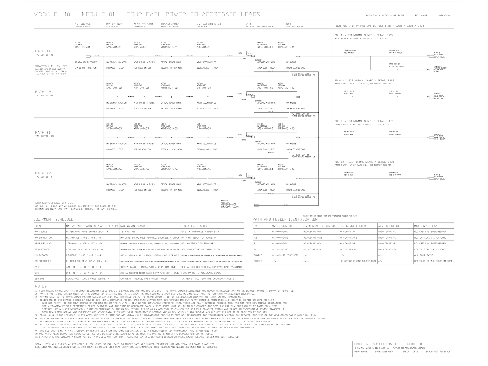
Take any single medium-voltage section on the current sheet, delete it, and write down the low-voltage paths that go with it. Wherever that list has two entries under a claim of two independent paths, the decoupling is not there. "Low-voltage A/B exists, therefore every level upstream is redundant" is carried in the architecture record as an excluded statement [FACT]. The consequence that has to be drawn rather than asserted is narrower: if medium-voltage bus ownership is allowed to coincide with the low-voltage A/B path identity, one medium-voltage event removes both nominal paths together. On the current record the required decoupling is a requirement placed on the design, not a demonstrated property of it. No drawing reviewed here shows it.
The One-Line Shows Connectivity, Not Failure Domain
A one-line drawing is a connectivity document and it is not in dispute here. Two paths drawn from separate low-voltage boards to dual-supply racks are two paths. The drawing is telling the truth about what is connected to what. What it does not carry is the set of single events that remove more than one of those paths at once. That set is decided several levels upstream, by which medium-voltage section owns which transformer.
The closure record is precise about this split. It accepts that the healthy UPS path in the strict two-path arrangement has 14 MW [MODELED] against a 12.711 MW [MODELED] protected load. In the same row it requires medium-voltage bus identity to be decoupled from low-voltage path identity, recording the capacity as accepted and the failure domain as still to be proven [FACT]. Capacity and domain are answered by different documents. Only one of them has been answered.
Four Transformers on One Ring Share a Cable-Fault Domain
Section counts on the medium-voltage lineup vary by arrangement in a way that looks like a space and cost question and is not:
two independent lineups, radial feeders        33 sections
single lineup, ring grouping (4 per ring)      25 sections + 14 local two-way switching units
single lineup, per-unit primary selection      45 sections
The ring-grouped option is the one the basis leans toward, and it states its own cost in the same breath. Four transformers on a ring share one pair of feeder cubicles, so a cable fault inside the ring affects all four at once. That is described as failure-domain amplification and made conditional on scenario verification, with an explicit fallback: if the Engineer of Record judges ring-internal common cause unacceptable, the arrangement reverts to per-unit primary selection and twenty sections are added [FACT].
Read the three lines again as domain sizes rather than as quantities. The difference between 25 and 45 sections is not twenty cubicles of steel. It is whether one cable fault can reach four transformers or one. Everything the low-voltage layer claims about independence is downstream of that choice.
Capacity accepted, domain unproven
In the strict two-path arrangement, the failure matrix has bus differential isolating the fault, dual-supply load shifting to the healthy path, and the faulted path rebuilt from on-site generation. The healthy UPS path carries 12.711 MW within its 14 MW [MODELED]. Note that the electrical answer and the utility answer diverge at this point. The surviving utility feeder still cannot carry the whole facility — the two allocations are 8 MW [TARGET] and 7 MW [TARGET], each smaller than facility demand — so a medium-voltage event that the low-voltage layer absorbs may still be a generation event at the service interface. The evidence the matrix demands before that row closes is bus-differential selectivity, path identity not bound to a single medium-voltage bus, and a transfer power-flow study.
In the three-system arrangement, two healthy systems total 16 MW [MODELED] against the same 12.711 MW, conditional on the three systems not being removable by a single medium-voltage or ring event — the same ring common cause, now applied to whole systems instead of single transformers. In the catcher arrangement the single-block capacity holds, while the proposition that one medium-voltage event removes at most one block is recorded as unproven.
One element is common to all three, and it is the reason this belongs on a drawing rather than in a memo: in every case the capacity arithmetic is accepted and the failure domain is not. The capacity table produces identical numbers whether the decoupling exists or not. No amount of checking it will detect the problem.
Each MV Section Must Map to the LV Paths It Can Remove
Path identity has to become an attribute that objects carry, not an inference a reader draws from line colour or from a panel name that happens to end in A. Each medium-voltage section and each ring has to be mapped to the set of low-voltage paths it can remove. That mapping is the document an availability question gets answered from. The one-line remains correct, and remains the wrong sheet to ask.
A second consequence attaches to the single-lineup options specifically. Compressing the whole site onto one lineup makes that lineup a site-wide common cause. The basis records arc-resistant construction, bus differential protection and compartment segregation as not optional in that case [FACT]. Those costs have to sit inside the single-lineup option when it is compared against two lineups, or the comparison is measuring the wrong thing.
Neither consequence releases anything for purchase. No arrangement is selected. The record prohibits freezing the final choice, the equipment orders and the final section count.
Limits and open items
Confirmed: low-voltage A/B does not establish upstream redundancy; medium-voltage bus assignment must be decoupled from the low-voltage redundancy paths; ring grouping at four transformers per ring amplifies the domain to four transformers per cable fault; arc-resistant construction and bus differential are required in the single-lineup cases. [FACT]
Study values, not frozen: the 33, 25-plus-14 and 45 section counts; the 14 MW and 16 MW surviving figures; the 12.711 MW protected load; and the 2,000 A [MODELED] bus continuous rating. [MODELED]
Open before any of this closes: the Engineer of Record determination on ring-internal common cause; bus-differential selectivity settings; the transfer power-flow study; the serving utility system short-circuit contribution, which is a blocking item and leaves every interrupting rating open; and the choice of arrangement itself, which is not made. [HOLD]
Nothing here has been reviewed or sealed by an Engineer of Record. Nothing describes how any installed system behaved.
How Many Sections Has Anyone Actually Deleted on Paper
If ring-internal common cause is ruled acceptable by the Engineer of Record, and the rack pairing matrix is machine-verified so that no rack has both supplies inside one ring, the single-lineup arrangement can hold its nominal redundancy and this concern reduces to a documentation requirement. Absent either half, the number of low-voltage paths is not a statement about anything.
The test for that is cheap, and it is a drawing test rather than a study. How many sections on your current sheet has anyone actually run that deletion on?
© 2026 K&K Data Service Inc. All rights reserved. Reproduction or republication is permitted only with clear attribution to K&K Data Service Inc. and a working hyperlink to the canonical URL of this article. Excerpts must preserve the technical context, maturity labels, assumptions, and limitations. No excerpt may imply project approval, field validation, certification, or endorsement that the original article does not state.
Source: K&K Data Service Inc., “Matching MV Bus Identity to LV A/B Deletes Both Redundant Paths,” https://www.kkdatasvc.com/lab/electrical-architecture-and-failure-domains/if-the-mv-bus-equals-a-b-one-event-deletes-the-redundant-path/.
Challenge This Diagram. If your project record shows a different result, or the same failure domain under another name, we want to see it. Email inquiry@kkdatasvc.com or use the contact page.