
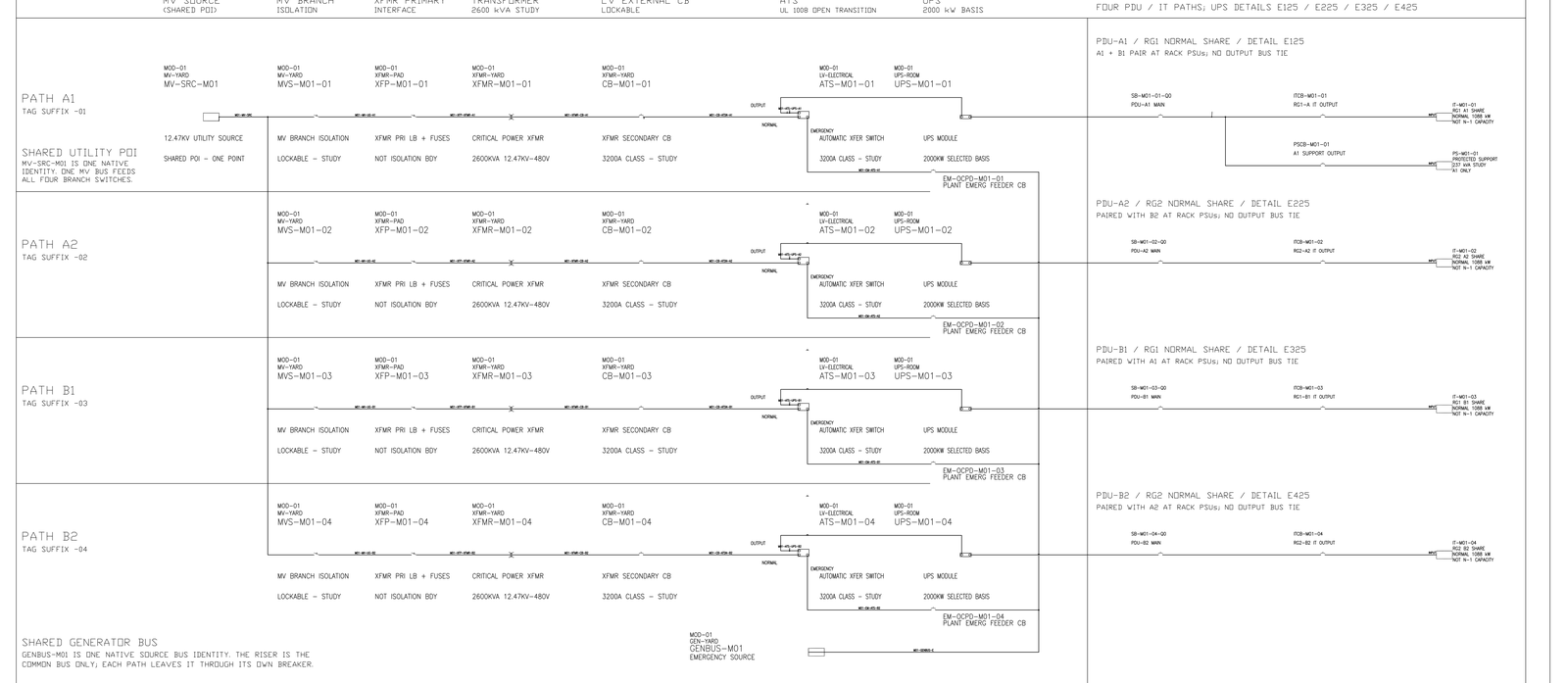
Does moving from strict low-voltage 2N to a three-system arrangement return a generating unit? Gate 1 priced Route B as about 25 % [MODELED] less installed uninterruptible-supply and transformer capacity — twelve 2 MW [MODELED] units against fourteen, and about nine 2.5 MVA [MODELED] transformers against twelve. The on-site generation count does not move with it. Generation is sized against facility demand and site-level N+1, and 8 × 2.5 MW [MODELED] remains the study basis across all three candidate topologies. The two variables that do change the count are an equipment supplier's derating table and a control interlock.
The LV Routes Change UPS Count, Not Generator Count
The architecture record compares the routes on the quantities they genuinely affect. Route A puts the uninterruptible output onto dual power-supply inputs as two complete paths, each independently carrying 100 % of the agreed information-technology load, at six 2 MW units per path — twelve, or fourteen with module-level redundancy per path. Route B runs three independent systems at about 4 MW [MODELED] each in normal operation, with any one system's loss leaving the other two at about 6 MW [MODELED] each.
Both routes are stated with their costs attached. Route A is easier to define and easier to audit at the rack. Route B reduces capital, space, maintenance and installed battery energy, and pays for it with a harder rack pairing matrix, harder protection and transfer design, and a more demanding integrated systems test. Neither of those cost lists contains generator quantity, and the reason is structural rather than incidental.
The later quantity derivation prices the uninterruptible-supply save at 14 % [MODELED], not 25 %. Twelve modules against fourteen is 24,000 kW [MODELED] installed against 28,000 kW [MODELED]. The 25 % talking point was a nine-unit count that does not close against 12.711 MW [MODELED] of protected load. Generation still does not move. Generators are a plant-level resource. They do not belong to any uninterruptible path.
Generators Are Sized to Plant-Level N+1, Not UPS Paths
Generation picks up facility demand, not protected load. It therefore sees the mechanical, house and medium-voltage loss components that sit outside the uninterruptible path, and it sees them identically whichever low-voltage topology is chosen, because changing how protected load is subdivided does not change how much of it there is. 12 MW [TARGET] of billable IT is the load the low-voltage route quantities were first derived from. It is not the quantity generation is sized on.
Run on the heat-rejection basis's steady facility figure of 14,125 kW [MODELED], seven units at the study net rating of 2.25 MW [MODELED] carry the load with 1,625 kW [MODELED] to spare — 11.5 % [MODELED] — and the site-level N+1 condition holds with the eighth unit. N-state capacity is 15,750 kW [MODELED] at the study derate. The subdivision of the low-voltage layer appears nowhere in that calculation. A designer who expects Route B to return a generator is confusing a reduction in redundant conversion capacity with a reduction in load, and only the second would change the count.
An earlier electrical basis had 7 × 3.0 MW [MODELED] as the generation study case. The task book later forced 2.5 MW, which is why the count became eight. That conflict is still open. It is a nameplate-grade conflict, not a topology conflict.
Derate and lockout move the count
Derating is the first and the larger. The study currently assumes 0.90 [MODELED] for site conditions, giving 2.25 MW net per 2.5 MW unit and 15,750 kW in the N configuration. The shared engineering register prohibits freezing that value. If the supplier's table returns 0.85 [SENSITIVITY], the N+1 available capacity falls from 15,750 to 14,875 kW [SENSITIVITY] and the 1,625 kW margin becomes 750 kW [SENSITIVITY] — a change in headroom larger than anything either low-voltage route contributes, driven by a document nobody on the project has yet.
Battery-recharge lockout during generator operation is the second and the subtler. Without the interlock, generator-side demand rises by the recharge component from 14,125 to 14,358 kW [MODELED], cutting the margin from 1,625 to 1,392 kW [MODELED]. That alone does not add a unit in the base column. In the least favourable modelling column it does: the peak reaches 16,768 kW [MODELED], eight units are required, and in one corner case of 16,668 kW [MODELED] N+1 becomes nine. The heat-rejection basis draws the conclusion carefully — the interlock is not there to save a generator, it is there to stop the unit count turning over a second time under the least favourable branch — and requires it to be written into the control specification rather than left to operating practice.
On the base column, lockout or not, seven units still carry. On the conservative column times 581.8 kW [MODELED] of fast charge, N+1 goes from eight to nine. That is a generation-and-control problem. It is not a low-voltage topology problem.
Limits and open items
Confirmed: generation is site-level N+1 and is sized on facility demand; the study basis of 8 × 2.5 MW is common to the candidate topologies; the low-voltage route affects uninterruptible-supply, transformer and battery quantities and not generator quantity. [FACT]
Modelled and expressly unfrozen: the 0.90 derating and the 2.25 MW net rating, the 15,750 kW N-state capacity, the 14,125 and 14,358 kW facility figures and the 1,625, 1,392 and 750 kW margins. The unit counts on both low-voltage routes are preliminary and the architecture record forbids freezing transformer, uninterruptible-supply, battery, generator and switchgear quantities or entering supplier orders. [MODELED]
Held: the supplier derating table, the customer's position on whether each of A and B must independently carry 100 % of protected load, and written permission for any arrangement in which on-site generation runs alongside the utility supply. [HOLD]
Nothing above reflects Engineer of Record review, serving-utility consent, equipment supplier confirmation, commissioning acceptance or observed plant behaviour.
Ask for the Site-Condition Derate Table First
A single returned document reopens all of this, and it is not a low-voltage document. If the derating table comes back at 0.85, or lower once altitude, ambient temperature and harmonic loading are taken together, the count discussion restarts on a variable that neither Route A nor Route B touches.
The request worth issuing first is therefore narrow: what is the site-condition derating curve, and at what ambient and altitude was each point on it established?
© 2026 K&K Data Service Inc. All rights reserved. Reproduction or republication is permitted only with clear attribution to K&K Data Service Inc. and a working hyperlink to the canonical URL of this article. Excerpts must preserve the technical context, maturity labels, assumptions, and limitations. No excerpt may imply project approval, field validation, certification, or endorsement that the original article does not state.
Source: K&K Data Service Inc., “Low-Voltage UPS Topology Does Not Reduce On-Site Generator Count,” https://www.kkdatasvc.com/lab/ups-battery-and-generation/lv-topology-does-not-buy-you-fewer-generators/.
Discuss This Constraint. If your project record shows a different result, or the same failure domain under another name, we want to see it. Email inquiry@kkdatasvc.com or use the contact page.